Damper vane and housing construction

Active Publication Date: 2013-10-17
AIRFIXTURE
View PDF3 Cites 2 Cited by
  • Summary
  • Abstract
  • Description
  • Claims
  • Application Information

AI Technical Summary

Benefits of technology

The present invention is about dampers that reduce airflow when closed and allow for wider tolerances between the vane and the housing when not closed. It helps in designing a housing that allows for greater flexibility in the movement of the damper.

Problems solved by technology

However, because the edges of the vane do not contact the frame, air may still pass around the edges of the vane between the vane and the walls of the frame.
However, tolerances become very critical.
If the walls of the frame are not parallel and square, the vane can rub on the metal walls, creating wear, noise, and decreased product life.
This gap results in continual air passage around the vane, even when it is in the closed position.

Method used


Image

  • Damper vane and housing construction
  • Damper vane and housing construction
  • Damper vane and housing construction

Examples


Embodiment Construction

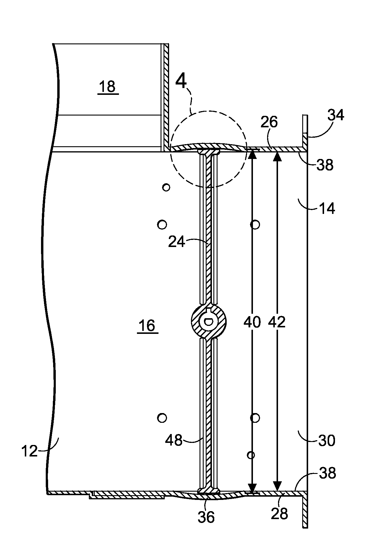
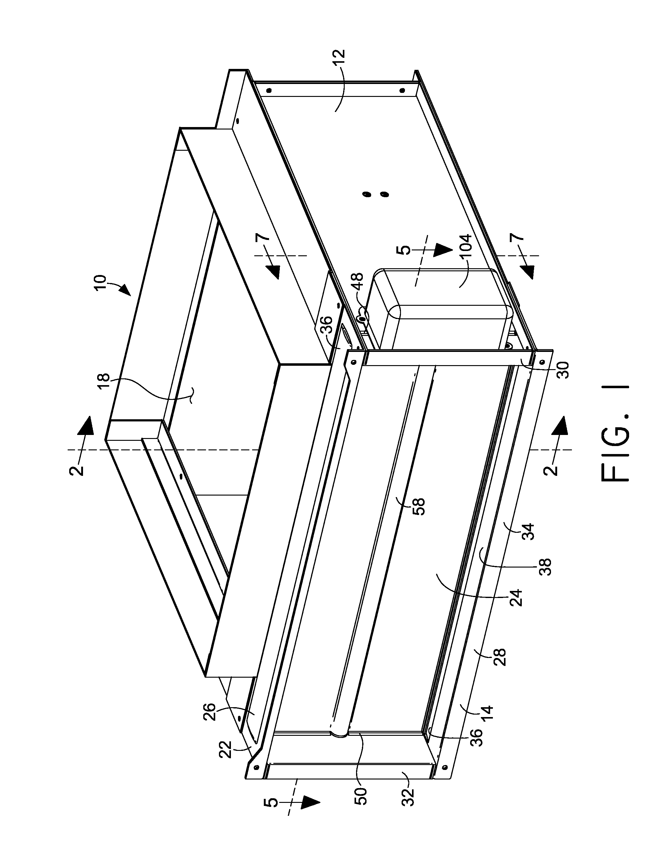
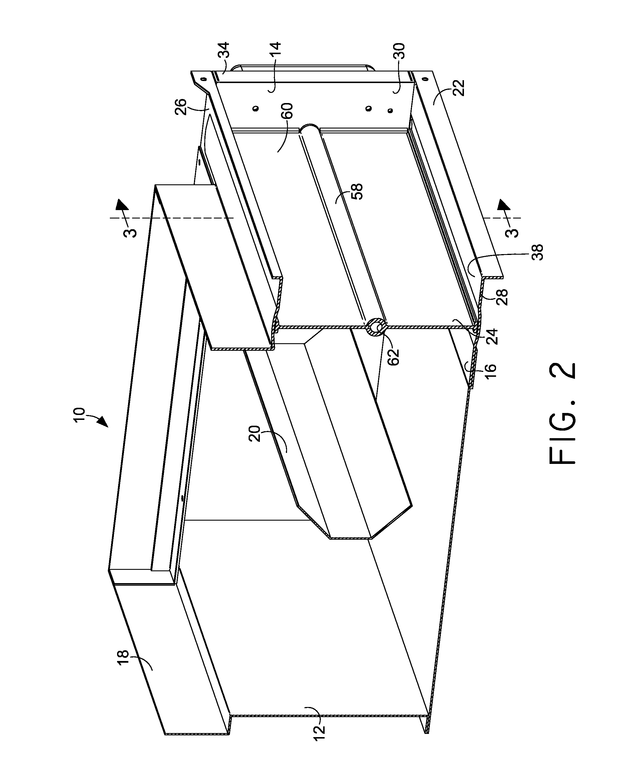
[0025]Referring now to the drawings in more detail and initially to FIG. 1, numeral 10 generally designates an air terminal constructed in accordance with an embodiment of the present invention. The air terminal 10 has an air delivery assembly 12 coupled with a damper 14. The air terminal 10 may be positioned in an opening in a raised floor air distribution system (not shown) to control the passage of conditioned air from a plenum under the raised floor up into a room to be heated or cooled. The air delivery assembly 12 generally defines a box-like structure having a lateral opening 16 and a top opening 18. The lateral opening 16 is covered by the damper 14, which selectively controls the flow of air into the air delivery assembly 12. The air then exits the air delivery assembly 12 up through the top opening 18 and flows into the room.

[0026]The top opening 18 may receive a grate or grate assembly (not shown) to cover the top opening 18, but still let air to flow therethrough. The ai...


PUM


Abstract

A damper having a housing includes a rotatable damper vane therein constructed to minimize the passage of air between the vane and the housing when the vane is in a closed position. The housing includes a pair of opposed walls having a channel or flute therein adjacent outer edges of the vane when the vane is in the closed position. The outer edges of the vane terminate in domed or arcuate shaped surfaces that generally correspond with the channel. The arcuate shaped surfaces are a distance apart that is greater than a distance between the opposed walls such that the arcuate shaped surfaces are received in the channels when the vane is in the closed position. The housing also includes a pair of opposed sidewalls having a ridge therein at a location that aligns with an edge of the vane when the vane is in the closed position.

Description

CROSS-REFERENCE TO RELATED APPLICATIONS[0001]Not applicable.STATEMENT REGARDING FEDERALLY SPONSORED RESEARCH OR DEVELOPMENT[0002]Not applicable.BRIEF SUMMARY OF THE INVENTION[0003]The present invention relates to damper vanes. More particularly, this invention relates to a damper construction that reduces the amount of airflow around a damper in a closed position while permitting construction of a housing that allows for greater tolerances between the vane and the housing in non-closed positions.[0004]Dampers consisting of a damper vane which rotates within a housing to selectively restrict and permit the passage of air through the housing are well known in the art. One particular construction known to be beneficial is disclosed in U.S. Patent Application Publication No. 2007 / 0066213 A1, which is incorporated herein in its entirety. It discloses a damper coupled with an air delivery assembly to create a floor terminal for use in a raised floor air distribution system. The vane of th...

Claims


Application Information

Patent Timeline
IPC IPC(8): F24F13/10
CPCF24F13/20F24F13/14F24F2013/1433
Inventor BRIAR, SCOTT MICHAELMCQUEENY, MICHAEL J.
Owner AIRFIXTURE
Why Eureka
Try Eureka