Multi-Stage Mechanisms For Event Detection and Initiation of Pyrotechnic Materials in Thermal Batteries and the Like in Munitions
- Summary
- Abstract
- Description
- Claims
- Application Information
AI Technical Summary
Benefits of technology
Problems solved by technology
Method used
Image

Examples
embodiment 200
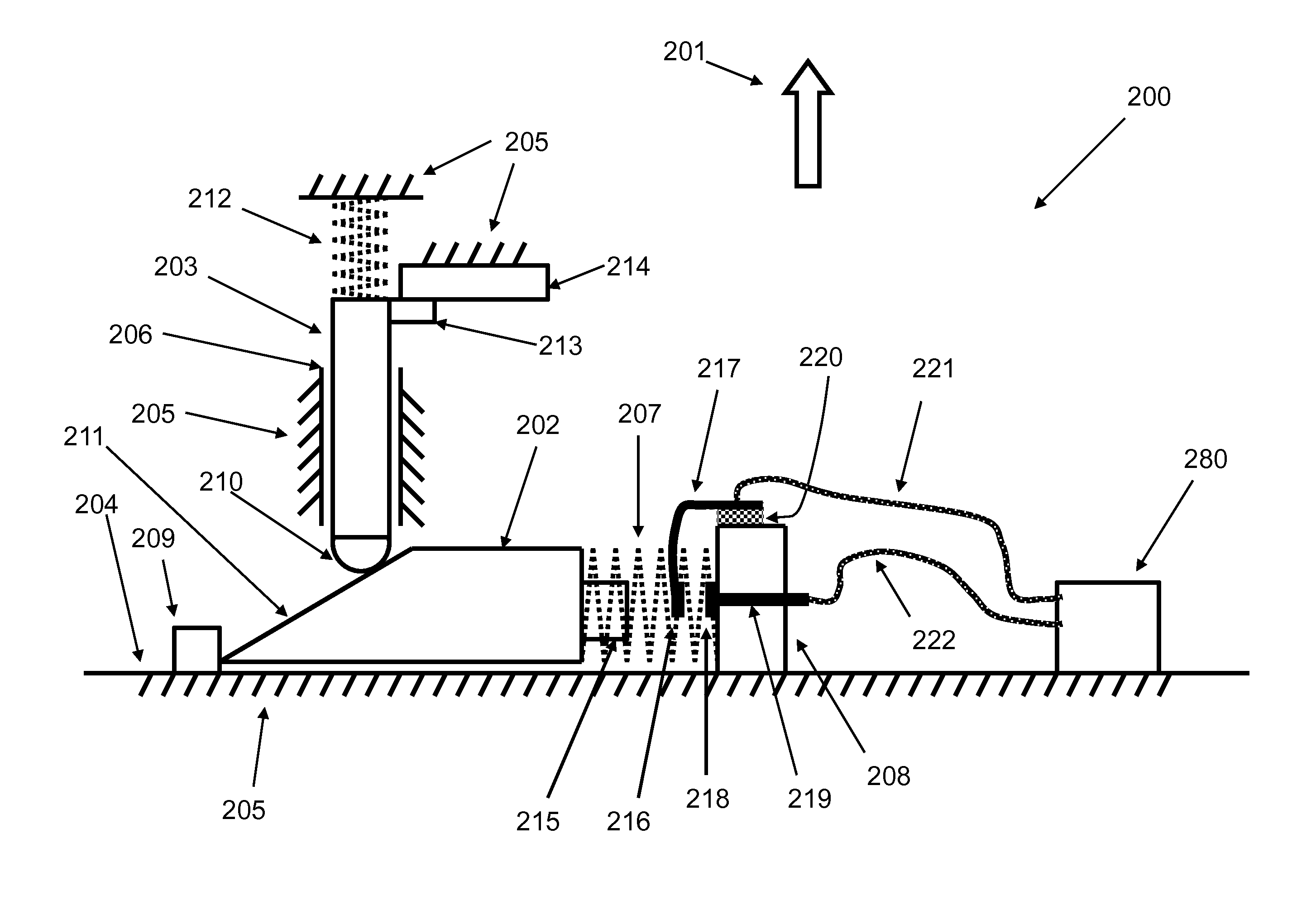
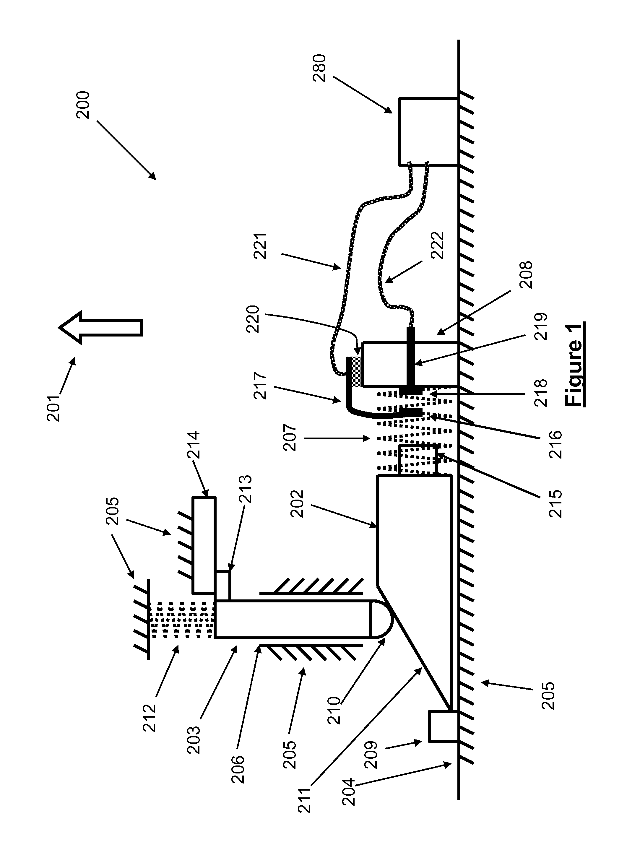
[0069]An embodiment 200 of a highly compact mechanisms and method for detecting “significant barrier” encounter events and providing the means to count the number of such encounter events for use in miniature inertial igniters for thermal batteries or other safe and arm devices and the like and their operation is shown in the schematic of FIG. 1. The device 200 is designed to close an electrical circuit by causing two contacts that keep the circuit open to come into contact when the device is subjected to an acceleration in the direction of the arrow 201 as a result of encountering a “significant barrier”, i.e., as a result of impact shock caused by the munitions encountering a “significant barrier”.
[0070]The device 200 mechanism consists of the main moving elements 202 and 203. The element 202 can slide back and forth (to the right and left as seen in the schematic of FIG. 1 over the surface 204 of the device structure 205. The element 203 is provided with a guide 206, which is pre...
embodiment 300
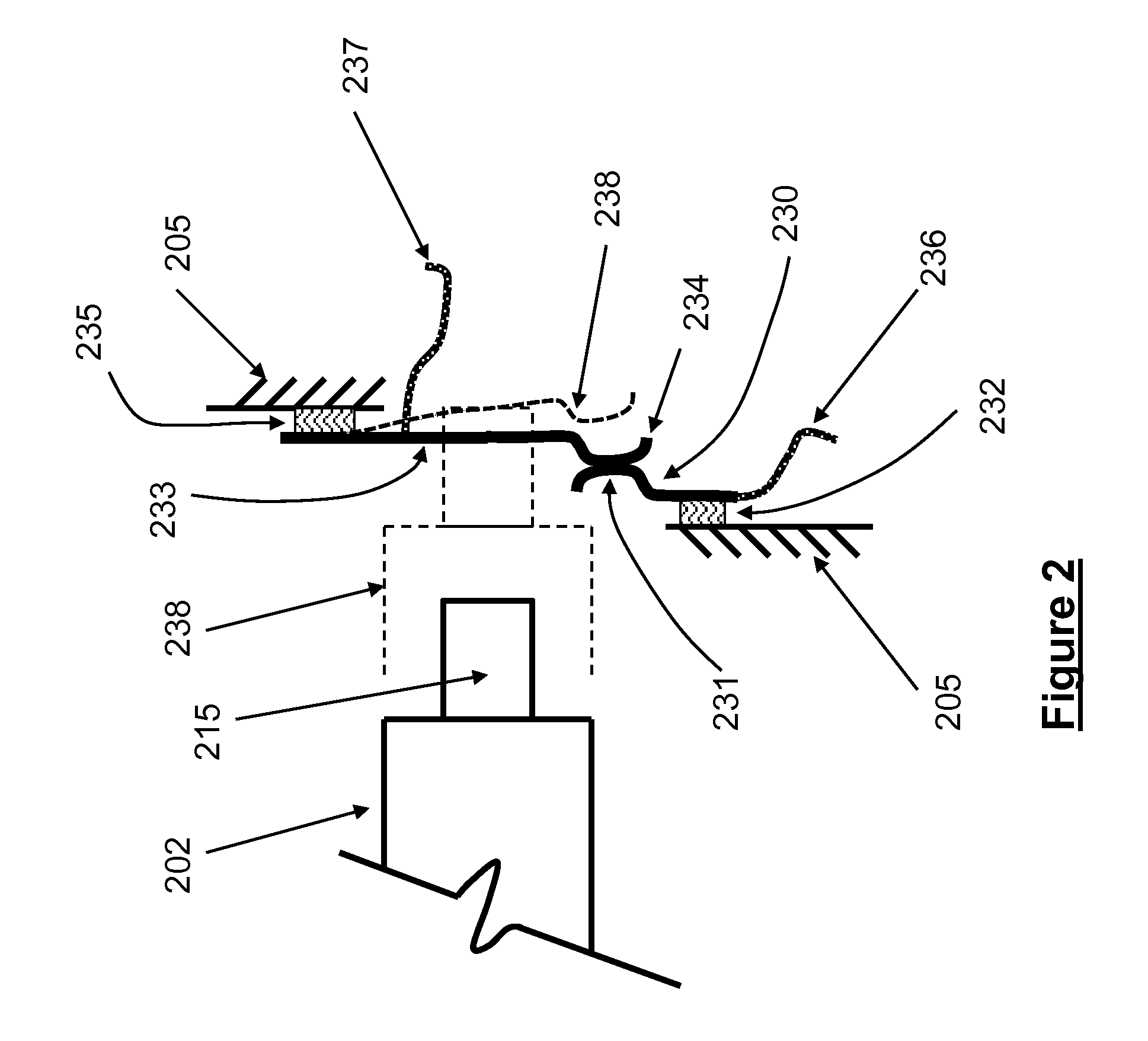
[0093]In one embodiment, at least two novel mechanisms 200 of the type shown in the schematic of FIG. 1, with the “significant barrier” detecting normally open contacts 216 and 218, or its alternative normally closed contacts shown schematically in FIG. 2, or their combinations, are used. Hereinafter and for the sake of simplicity, the embodiment 200 and its variations shown in FIGS. 1 and 2 are referred to as simply “barrier detectors”. Now consider the case in which the embodiment 300 shown schematically in FIG. 5 is constructed with three “barrier detectors” indicated by the numerals 301, 302 and 303. The “significant barrier” encounter detecting (“counting”) device 300 is intended to detect “significant barrier” encounters as well as their corresponding impact force levels. The three “barrier detectors”301, 302 and 303 are identical, except for the spring rates of one or both spring elements 207 and 212 and / or their amounts of preloading, and / or the inertia (mass) of element 202...
embodiment 400
[0114]In the embodiment 400, the rotary member 401 is attached to the device 400 structure 403 by the rotary joint 404. At least one engagement member 405 (three such members are shown in the schematic of FIG. 12) are attached at the base 406 to the rotary member 401 as shown in FIG. 12. Each engagement member 405 is provided with an “edge” member 407, which is fixed to the engagement member 405. The device 400 is also provided with a stop member 408, which is fixed to the device structure 403. The stop member 408 has certain thickness (in the direction perpendicular to the plane of FIG. 12), and can be constructed essentially as a relatively short cantilever beam. A lever 409 is also attached to the rotary member 401 at its end 410, and is attached to the spring 402 at its other end. The spring 402 is preloaded in tension. The side 411 of the edge member 407, in normal conditions, is at a level that would engage the side 412 of the stop member 408 when the rotary member 401 is rota...
PUM
 Abstract
Description
Claims
Application Information
 - R&D
- Intellectual Property
- Life Sciences
- Materials
- Tech Scout
- Unparalleled Data Quality
- Higher Quality Content
- 60% Fewer Hallucinations
Browse by: Latest US Patents, China's latest patents, Technical Efficacy Thesaurus, Application Domain, Technology Topic, Popular Technical Reports.
© 2025 PatSnap. All rights reserved.Legal|Privacy policy|Modern Slavery Act Transparency Statement|Sitemap|About US| Contact US: help@patsnap.com