Aqueous Urea Tank Structure for Construction Machine

a technology of aqueous urea and construction machines, which is applied in the direction of machines/engines, mechanical equipment, transportation and packaging, etc., can solve the problems of troublesome defrosting of aqueous urea, harmful nitrogen oxide in the exhaust gas emitted from the engine, etc., and achieve the suppression of damage to reduction of ammonia production, and suppression of corrosion and degradation of the aqueous urea tank

Inactive Publication Date: 2013-10-24
NIHON KENKI CO LTD
View PDF1 Cites 7 Cited by
  • Summary
  • Abstract
  • Description
  • Claims
  • Application Information

AI Technical Summary

Benefits of technology

[0019]An aqueous urea tank structure for a construction machine according to the invention is provided in the construction machine which has an engine disposed within a revolving upperstructure, and a hydraulic pump driven by the drive force of the engine, and the aqueous urea tank structure includes an aqueous urea tank which is disposed within the revolving upperstructure to store aqueous urea that purifies exhaust gas discharged from the engine. The aqueous urea tank structure for the construction machine further includes a securing member which encloses the periphery of the aqueous urea tank and secures the aqueous urea tank within the revolving upperstructure, and heat insulating materials which are interposed between the securing member and the aqueous urea tank to hold the aqueous urea tank. Accordingly, due to the heat insulating materials, the heat outside the securing member can be prevented from being transmitted to the aqueous urea tank. Therefore, the rise of the temperature of the aqueous urea in the aqueous urea tank can be suppressed so that the concentration of the aqueous urea can be kept within a fixed range. In addition, evaporation of the aqueous urea stored in the aqueous urea tank can be suppressed so that the amount of ammonia produced can be reduced. Thus, corrosion and degradation of the aqueous urea tank by the ammonia can be suppressed.
[0020]Further, in the aqueous urea tank structure for the construction machine according to the invention, the securing member encloses the periphery of the aqueous urea tank so as to secure the aqueous urea tank within the revolving upperstructure, and the heat insulating materials are interposed between the securing member and the aqueous urea tank so as to hold the aqueous urea tank. Thus, even when vibration occurs in a vehicle body due to work, the aqueous urea tank is prevented from moving inside the securing member. In addition, due to the heat insulating materials, the aqueous urea tank can be prevented from suffering strong stress locally from the securing member, so that the damage of the aqueous urea tank can be suppressed. In this manner, the rise of the temperature of the aqueous urea in the aqueous urea tank can be suppressed, while the load applied to the aqueous urea tank due to vibration of the vehicle body can be reduced. As a result, the temperature of the aqueous urea in the aqueous urea tank can be kept moderate and the durability of the aqueous urea tank can be improved, in comparison with the background art.

Problems solved by technology

Here, the exhaust gas emitted from the engine contains harmful nitrogen oxide.
It has been a fear that this work of defrosting the aqueous urea may be troublesome.

Method used


Image

  • Aqueous Urea Tank Structure for Construction Machine
  • Aqueous Urea Tank Structure for Construction Machine
  • Aqueous Urea Tank Structure for Construction Machine

Examples


first embodiment

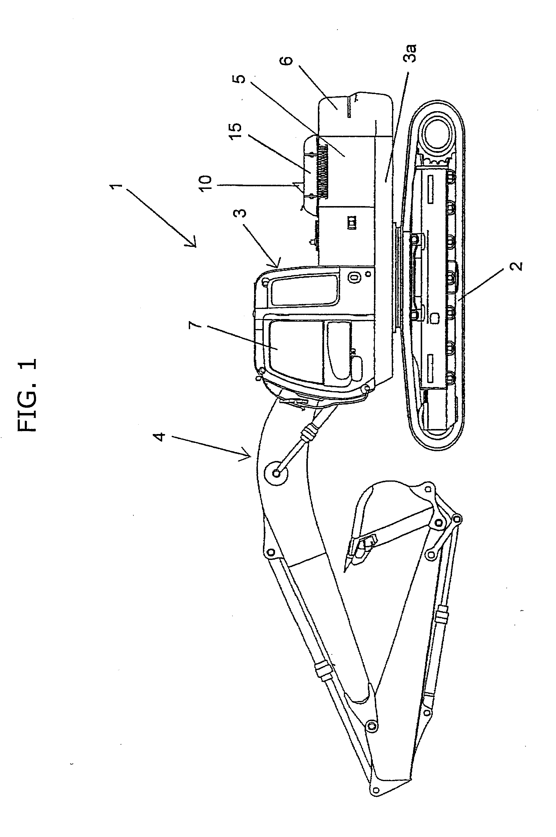
[0029]A first embodiment of an aqueous urea tank structure for a construction machine according to the invention is, for example, provided in a hydraulic excavator 1 as shown in FIG. 1. The hydraulic excavator 1 has a travel base 2, a revolving upperstructure 3 disposed on an upper side of the travel base 2 and having a slewing frame 3a, and a front work device 4 attached to the front of the revolving upperstructure 3 and revolving in an up / down direction. In addition, the revolving upperstructure 3 has a cab 7 in the front thereof and a counterweight 6 in the rear thereof. The revolving upperstructure 3 also has an engine room 5 between the cab 7 and the counterweight 6, and a vehicle body cover 15 disposed on an upper portion of the engine room 5. An exhaust port 10 through which exhaust gas emitted from an engine which will be described later is discharged to the outside is provided in the vehicle body cover 15.

[0030]The revolving upperstructure 3 has the engine which is not show...

second embodiment

[0046]FIG. 6 is a side view showing the configuration of a second embodiment of an aqueous urea tank structure for a construction machine according to the invention.

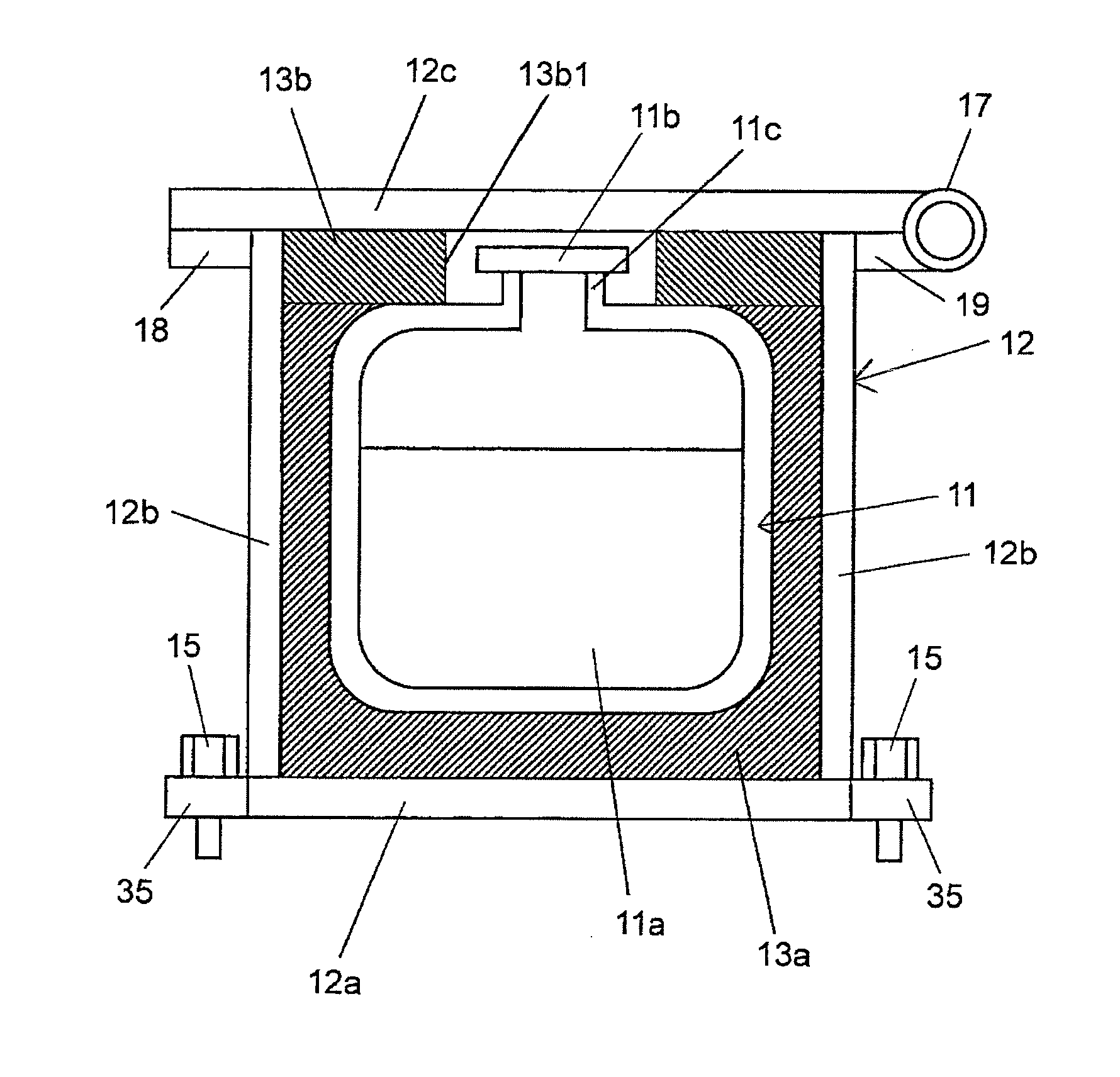
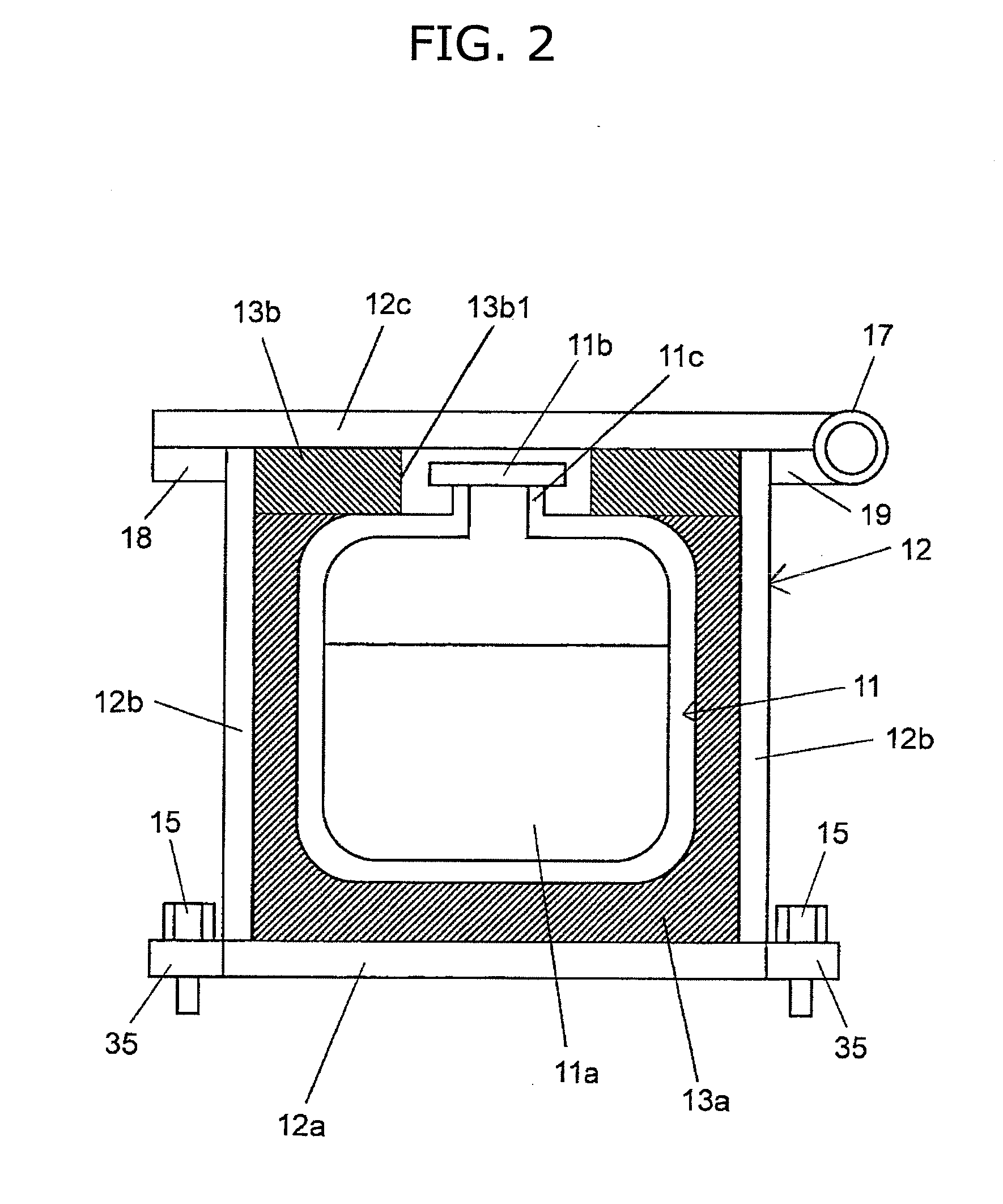
[0047]In the first embodiment, as shown in FIG. 2, the securing member includes the box 12, the heat insulating material 13a is laid between the box 12 and the lower portion and the side portions of the aqueous urea tank 11 so as to come into tight contact therewith, and the heat insulating material 13b is further inserted between the box 12 and the upper portion of the aqueous urea tank 11 so as to enclose the supply port 11c of the aqueous urea tank 11. The second embodiment of the invention is different from the aforementioned first embodiment in that heat insulating materials 13c, 13d1, 13d2 and 13e are disposed, for example, in some parts of a space between the box 12 and the aqueous urea tank 11 in the second embodiment as shown in FIG. 6.

[0048]In this case, the heat insulating material 13c is laid on the lower por...

third embodiment

[0052]FIG. 7 is a side view showing the configuration of a third embodiment of an aqueous urea tank structure for a construction machine according to the invention.

[0053]In the aforementioned first embodiment, as shown in FIG. 2, the heat insulating material 13a is laid between the box 12 and the lower portion and the side portions of the aqueous urea tank 11 so as to come into tight contact therewith, and the heat insulating material 13b is further inserted between the box 12 and the upper portion of the aqueous urea tank 11 so as to enclose the supply port 11c of the aqueous urea tank 11. The third embodiment of the invention is different from the first embodiment in that heat insulating materials are disposed, for example, in some parts of a space between the box 12 and the aqueous urea tank 11 in the same manner as in the second embodiment, and of the heat insulating materials, the heat insulating material provided on the bottom portion of the aqueous urea tank 11 is made of a r...


PUM


Abstract

An aqueous urea tank structure is provided for a construction machine, in which a temperature rise of the aqueous urea within the tank can be suppressed and the load applied to the tank due to vibration of a vehicle body can be reduced. The aqueous urea tank structure including an aqueous urea tank which is disposed within a revolving upperstructure of a hydraulic excavator to store aqueous urea that purifies the exhaust gas discharged from an engine, wherein the aqueous urea tank structure further includes a securing member which encloses the periphery of the aqueous urea tank to secure the aqueous urea tank within the revolving upperstructure, and heat insulating materials which are interposed between the securing member and the aqueous urea tank to hold the aqueous urea tank. The securing member contains a box.

Description

TECHNICAL FIELD[0001]The present invention relates to an aqueous urea tank structure for a construction machine, including an aqueous urea tank for storing aqueous urea that purifies exhaust gas discharged from an engine.BACKGROUND ART[0002]A construction machine such as a hydraulic excavator generally has a travel base which has a crawler belt or the like and travels, a revolving upperstructure which is disposed above the travel base and connected thereto through a slewing frame so as to slew in a left / right direction, and a front work device which is provided in front of the revolving upperstructure and has actuators so as to perform work such as excavation. The revolving upperstructure has an engine which is provided inside the revolving upperstructure, and a hydraulic pump which is driven by the drive force of the engine so as to supply hydraulic pressure to the actuators. In addition, the revolving upperstructure is also provided with an exhaust duct for discharging, to the out...

Claims


Application Information

Patent Timeline
Patent Type & Authority Applications(United States)
IPC IPC(8): F01N3/20
CPCF01N3/2066F01N2610/1406Y10T137/85978Y02A50/20Y02T10/12F01N3/24F01N3/08
Inventor KOBAYASHI, TAKAHIRONAKAMURA, TSUYOSHISATO, KENSUKEAZUMA, HIROYUKI
Owner NIHON KENKI CO LTD
Why Eureka
Try Eureka