Projected capacitive touch sensor with asymmetric bridge pattern

a capacitive touch sensor and bridge pattern technology, applied in the field of capacitive touch sensors, can solve the problems of high resistor-capacitor time constant (rctc) of horizontally and vertically arranged electrodes, the effect of affecting and the difficulty of adjusting the settling time of the touch sensor

Active Publication Date: 2013-10-24
ELO TOUCH SOLUTIONS INC
View PDF5 Cites 9 Cited by
  • Summary
  • Abstract
  • Description
  • Claims
  • Application Information

AI Technical Summary

Problems solved by technology

In either case, there is manufacturing cost associated with lamination of more than one piece of glass and with the fabrication of electrodes on more than one surface.
However, for touch sensors designed for 15″ diagonal displays and larger displays, long touch sensor electronic settling times become more problematic.
One problem with such large projected capacitive touch sensors is that the resistor-capacitor time constant (RCtc) of the horizontally and vertically arranged electrodes tends to be high and do not match.
This is especially problematic when used in conjunction with fixed drive frequency controllers in which the total scan time is determined by the maximum RCTc of the arranged electrodes.
This in turn impacts the rate at which a touch location can be determined, which may negatively impact user experience.

Method used


Image

  • Projected capacitive touch sensor with asymmetric bridge pattern
  • Projected capacitive touch sensor with asymmetric bridge pattern
  • Projected capacitive touch sensor with asymmetric bridge pattern

Examples


Embodiment Construction

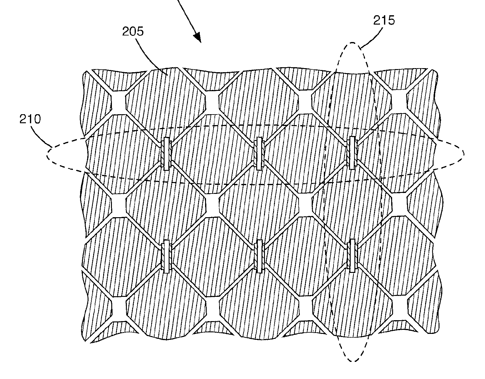
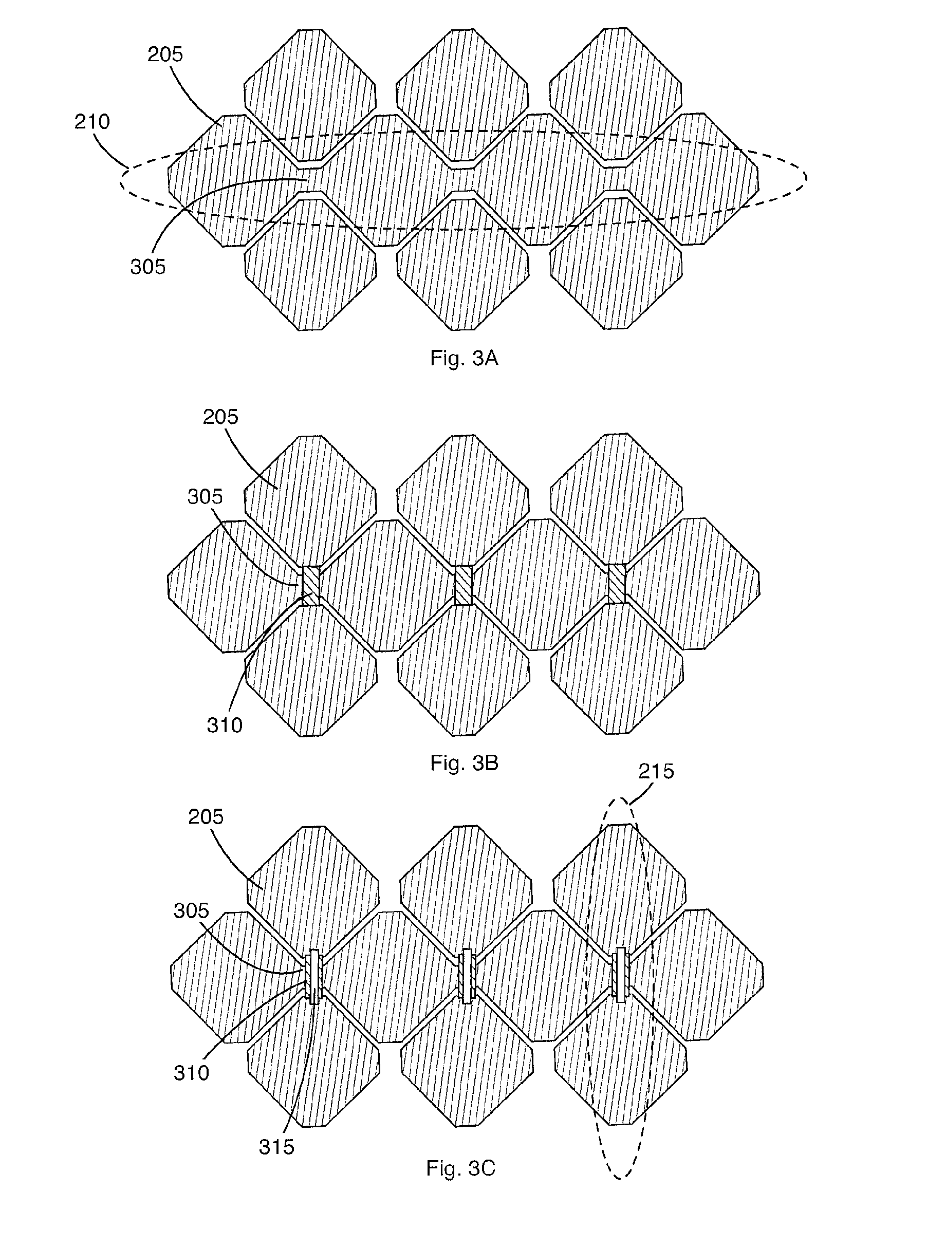
[0020]The embodiments described below overcome the problems discussed above by utilizing connections with asymmetric elements to couple the pads of the horizontally and vertically arranged electrodes.

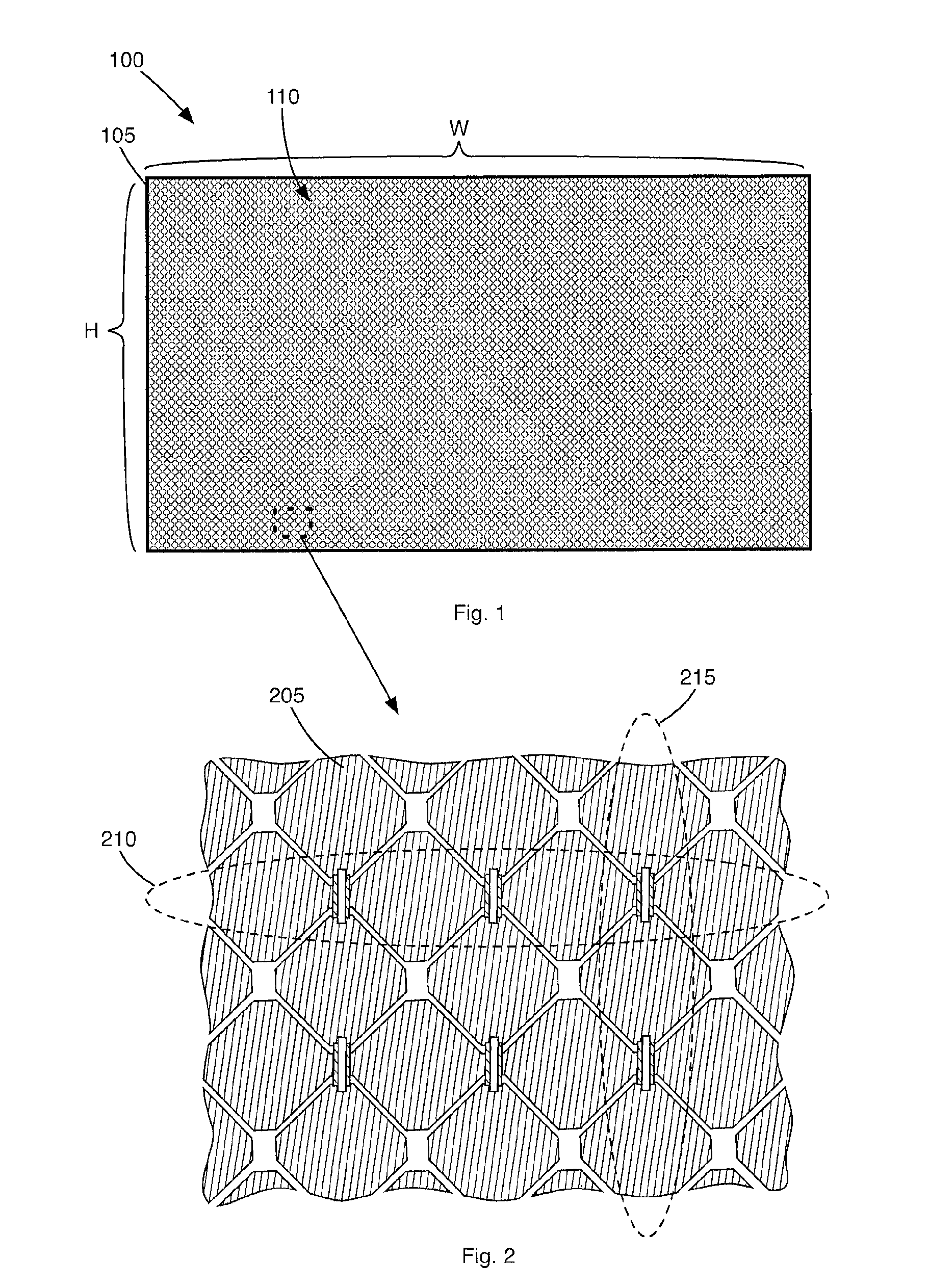
[0021]FIG. 1 illustrates capacitive touch sensitive device 100. The device 100 includes a substrate 105 upon which a electrode matrix 110 is arranged. The electrode matrix 110 includes a group of horizontally arranged electrodes and vertically arranged electrodes. In one exemplary embodiment, to accommodate a 16:9 display aspect ratio, the horizontally and vertically arranged electrodes fit within a rectangular area of the substrate that has a width, W, of about 477 mm and a height, H, of about 270 mm. Sixty-four vertically arranged electrodes and thirty-six horizontally arranged electrodes may be positioned within that area. In other words, the ratio of the number of vertically arranged electrodes to horizontally arranged electrodes may be about a 16:9. It is understood, however, that ...


PUM

PropertyMeasurementUnit
areaaaaaaaaaaa
heightaaaaaaaaaa
heightaaaaaaaaaa

Abstract

A capacitive touch sensitive device includes a matrix of pads patterned in a first electrically conductive material on a substrate. Horizontally adjacent pads within each even row of the matrix are electrically coupled to one another via channels to form a plurality of horizontally arranged electrodes. Insulators are positioned over respective channels. Conductive links are formed over respective insulators and are configured to electrically couple vertically adjacent pads between odd rows of the matrix to form a plurality of vertically arranged electrodes. The dimensions of the channels and the conductive links are configured such that an RC time-constant (RCtc) of each of the vertically arranged electrodes substantially matches an RCtc of each of the horizontally arranged electrodes.

Description

BACKGROUND[0001]1. Field[0002]The subject matter disclosed herein relates generally to capacitive touch sensors, and more particularly to a projected capacitive touch sensor with an asymmetric bridge pattern.[0003]2. Description of Related Art[0004]Projected capacitive touch sensors typically include a substrate upon which sensing electrodes are disposed. The substrate may be a durable glass having high optical transparency for viewing images displayed by an underlying display device that displays images such as graphical buttons and icons. When a user touches the outer surface of the substrate at a location corresponding to a desired selection displayed on the display device, the location is determined by sensing a change in the capacitance of the sensing electrodes.[0005]In some projected capacitive touch sensors, the sensing electrodes are arranged in rows and columns. The rows and columns comprise pads that are generally arranged in the form of a matrix. Horizontally adjacent pa...

Claims


Application Information

Patent Timeline
Patent Type & Authority Applications(United States)
IPC IPC(8): H03K17/96
CPCH03K17/9622G06F3/0443G06F3/0446G06F2203/04103G06F2203/04111Y10T29/49155
Inventor SON, KYU-TAK
Owner ELO TOUCH SOLUTIONS INC
Why Eureka
Try Eureka