Sensor-carrier cap for a bearing of a wheel hub

Active Publication Date: 2013-10-24
AB SKF
View PDF16 Cites 4 Cited by
  • Summary
  • Abstract
  • Description
  • Claims
  • Application Information

AI Technical Summary

Benefits of technology

[0004]One object of the present invention is to provide a simpler cap which is more economical to m

Problems solved by technology

This reinforcement of metallic material not only increases the production cost of the sensor-carrier caps described

Method used


Image

  • Sensor-carrier cap for a bearing of a wheel hub
  • Sensor-carrier cap for a bearing of a wheel hub
  • Sensor-carrier cap for a bearing of a wheel hub

Examples


Embodiment Construction

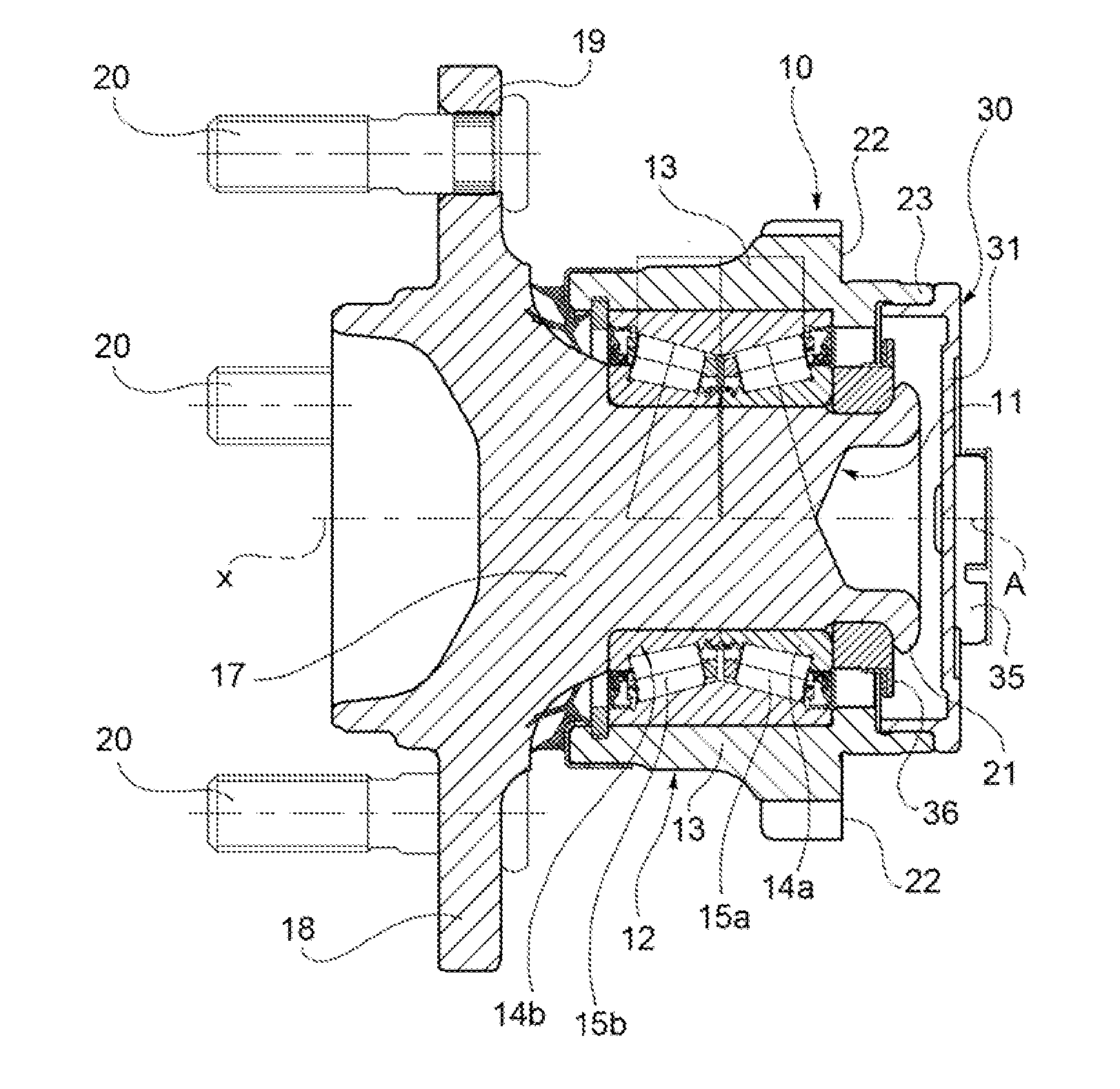
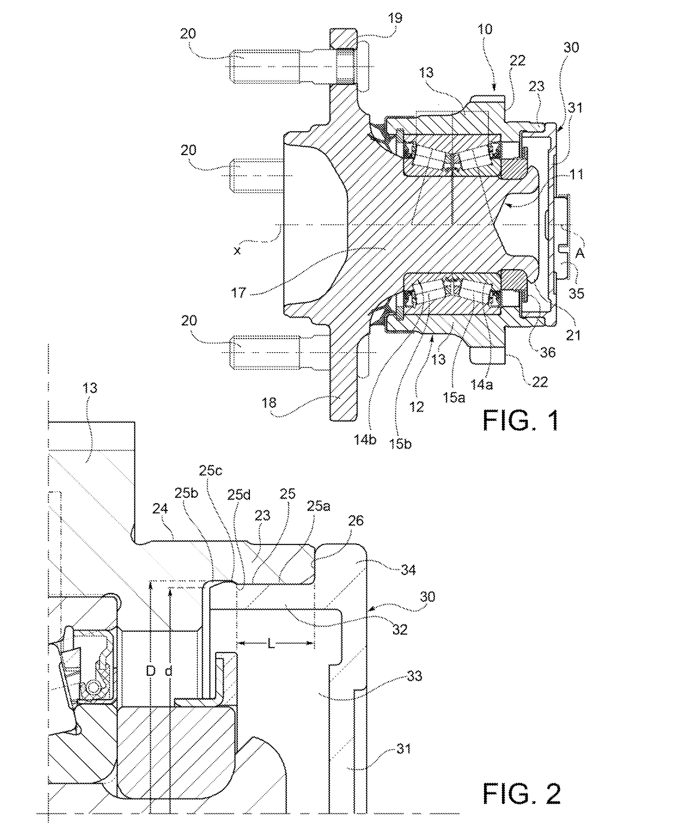
[0011]FIG. 1 shows a hub-bearing assembly indicated as a whole by the number 10. In the embodiment shown in FIG. 1, the assembly 10 is of the third generation type for a driven wheel (not shown) of a motor vehicle. The assembly 10 comprises a central hub 11 rotatable about a central axis X of rotation, and a rolling bearing 12 which includes a fixed ring 13 positioned radially outside the hub 11, a pair of radially inner, axially adjacent rings 14a, 14b, and a double row of rolling elements, which in this example are conical rollers 15a, 15b. Throughout the present description and the appended claims, any terms and expressions indicating positions and directions, such as “radial” and “axial”, are to be understood as referring to the axis of rotation x. On the other hand, expressions such as “axially inner” or “axially outer” relate to a condition in which the hub-bearing assembly is mounted on a motor vehicle.

[0012]The hub 11 forms a central cylindrical portion 17 with an integral f...


PUM


Abstract

A sensor-carrier cap for a bearing of a wheel hub, the cap being made of plastic material and having a bottom wall arranged transversely to a central axis and providing a seat for accommodating a sensor, a cylindrical mounting wall extending axially from one side of the bottom wall around the axis; snap locking means projecting in a radially outer direction from the cylindrical wall, for locking the sensor-carrier cap on a tubular appendage of a wheel hub-bearing.

Description

CROSS-REFERENCE TO RELATED APPLICATIONS[0001]This application claims priority to French patent application no. 1253676, filed Apr. 23, 2012, the contents of which are fully herein incorporated by reference.FIELD OF THE INVENTION[0002]The present invention relates to a sensor-carrier cap for a bearing of a wheel hub. The invention also relates to a hub-bearing assembly for a motor vehicle wheel.BACKGROUND OF THE INVENTION[0003]There are known sensor-carrier caps made of plastic material, comprising a bottom wall which has a seat for accommodating the sensor and a lateral cylindrical interface wall for mounting the cap in a wheel hub assembly. The cap is mounted in the wheel hub assembly by interference between the interface wall and an outer ring of the wheel hub assembly. The lateral mounting wall is usually provided with a reinforcement made of metallic material which stiffens the wall. See, for example, US 2006 / 159377 A1. In some applications, the metal reinforcement is positioned...

Claims


Application Information

Patent Timeline
IPC IPC(8): B60B27/00
CPCB60B27/0068B60B27/00B60B27/001B60B27/0073B60B2320/52B60B2360/32B60B2900/112B60B2900/115B60B2900/141B60Y2200/10F16C19/386F16C33/723F16C41/007F16C2226/74F16C2326/02Y10T403/60
Inventor CIULLA, LUCAFINETTI, WILLIAMWEBER, PHILIPPE
Owner AB SKF
Why Eureka
Try Eureka