
Peripheral sealing arrangement

Active Publication Date: 2013-10-24
IMO HOLDING GMBH
View PDF13 Cites 3 Cited by
  • Summary
  • Abstract
  • Description
  • Claims
  • Application Information

AI Technical Summary

Benefits of technology

The present invention offers an improved sealing solution that provides stable positioning, particularly against expulsion from the bearing. This is achieved through the use of a material protrusion on one of the bearing components, which allows for the sealing arrangement to be securely fixed in place. The technical effects of this invention include reduced disadvantages and improved sealing performance.

Problems solved by technology

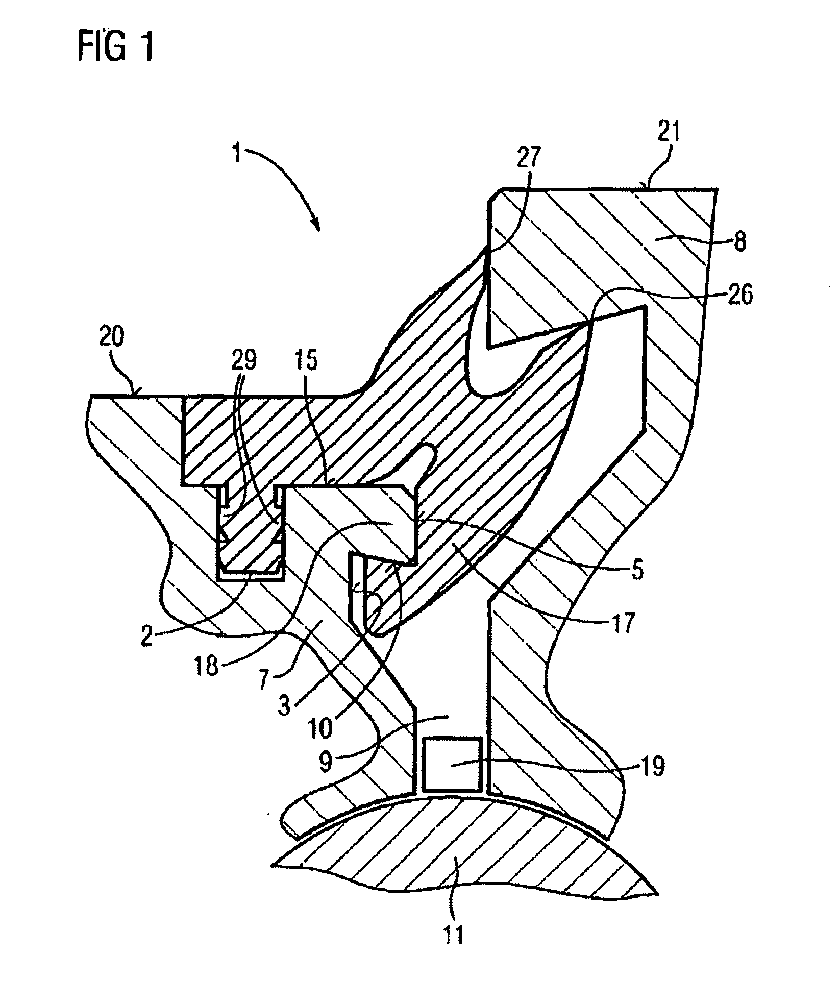
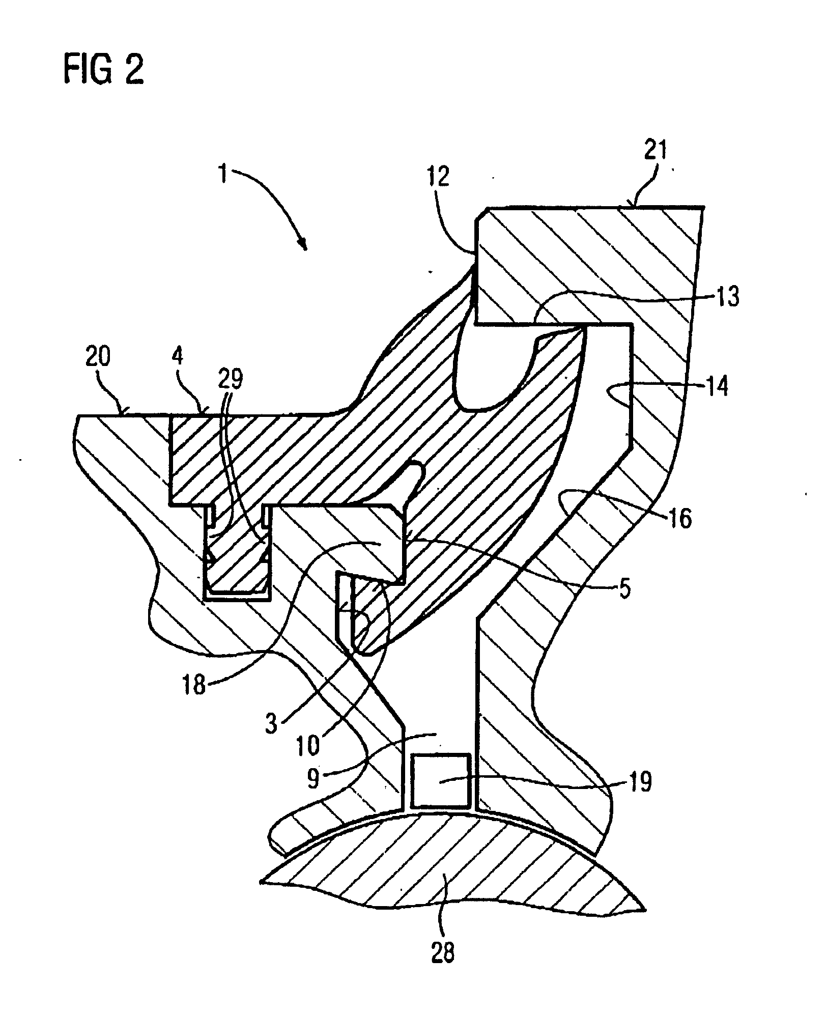
The disadvantageous problems of the conventional prior art can be solved, in particular, if the sealing arrangement according to the invention, or the element for sealing the assembly to be sealed, is provided with a geometry such that it is always able to remain in place, integrated in the structure as a whole, i.e., without dropping out, on its own and without the involvement of other components, both when the rotary joint is operating and during idle periods.

Method used


Image

  • Peripheral sealing arrangement
  • Peripheral sealing arrangement
  • Peripheral sealing arrangement

Examples


Embodiment Construction

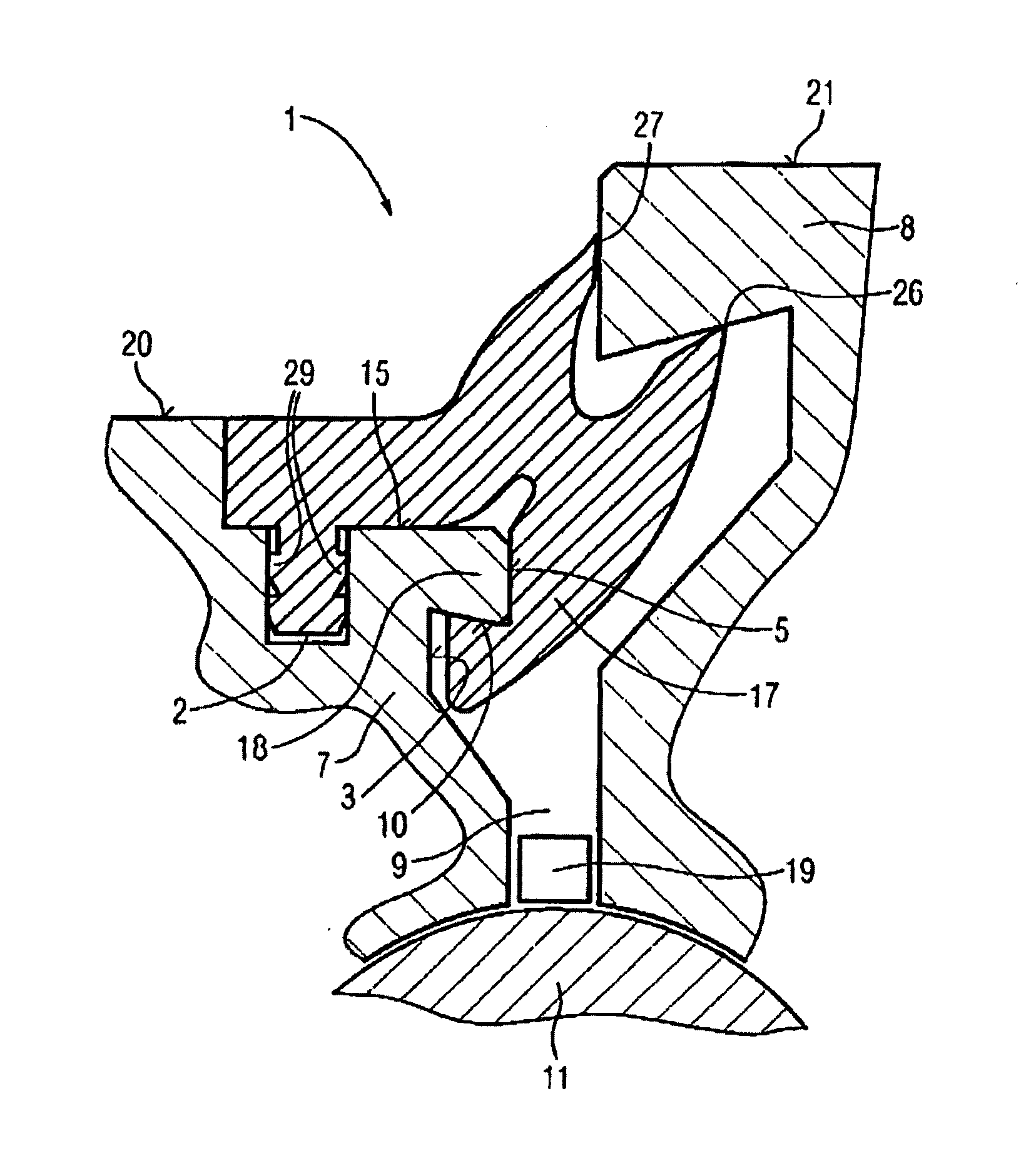
[0041]The sealing arrangement, according to the invention, sealing the sealing space or bearing gap, is made from a one-piece, peripheral, rubber-like sealing material. The main component of a pressure load from the bearing is absorbed by a bearing-side region of the seal. The seal is inserted, for example, between the outer ring and the inner ring of a rotary joint, the seal being equally well suited for use in rotary joints consisting of multi-piece outer or inner rings. To ensure the replaceability of the seal during field maintenance without the elaborate necessity of replacing the entire bearing, the sealing arrangement can be removed from, and put back into, the plunge cut in which it is fastened (for example, in order to replace the old seal with a factory-new one). The sealing arrangement is not fixed irretrievably in a groove, but is instead detachably and replaceably connected, an arrangement referred to as a form-locking and force-locking connection. Form-locking, on the ...


PUM


Abstract

The invention relates to a sealing arrangement made of a preferably integral peripheral rubber-like sealing material for sealing the sealing space for use in a rotary connection, wherein the sealing space is confined by a sealing region (17) on the bearing side and the sealing arrangement is used between at least one outer ring (or outer rotatable bearing component) (7) and at least one inner ring (or inner rotatable bearing component) (8) rotatable against one another about the same central axis, wherein the sealing arrangement is not irretrievably fixed in a groove but is connected by positive and non-positive engagement, so as to be releasable and replaceable again, to a recess (2) introduced on a surface parallel to the horizontal outer surface (20; 21) of the rotatable bearing component. The invention is in particular characterised in that a) for fixing by positive engagement on the outer or inner bearing component (7; 8) the sealing arrangement is retained by surrounding a projecting material protrusion (18) as an integral part of the outer or inner rotatable bearing component (7; 8), and b) said material protrusion (18) is surrounded by surfaces (10; 5; 15) which touch the sealing arrangement, and c) the sealing arrangement bears against a lower surface (10) on the bearing side of said material protrusion (18), which, as an abutment, supports the resistance against any axial pushing out from the direction of the sealing space (9) to be sealed.

Description

BACKGROUND OF THE INVENTION[0001]1. Field of the Invention[0002]The invention relates to a sealing arrangement comprising a preferably one-piece, peripheral, rubber-like sealing material for sealing the sealing space in a rotary joint.[0003]2. Description of the Prior Art[0004]Seals having an inner ring and an outer ring currently available commercially and in use for sealing rotary joints and slewing bearings, differ widely in shape and design, even though the uses are often very similar. The objective is always to protect the rotary joint or slew drive, or, in general, the slewing bearing or rolling bearing, reliably against external influences, for example moisture, wind-borne sand, contaminants or dirt, foreign bodies, etc.[0005]A practical sealing arrangement must also ensure resistance to the internal pressure of lubricant in the bearing. The seal should satisfy the requirements for preventing foreign bodies from getting into the bearing structure of the joint. At the same tim...

Claims


Application Information

Patent Timeline
IPC IPC(8): F16C33/74
CPCF16C33/74F05D2240/55F16C33/76F16C2300/14F16J15/3208F16J15/3232F16J15/3276F16J15/3456F16C2360/31F03D80/00F03D80/70F16C33/78F16J15/3236Y02E10/72
Inventor WILLACZEK, HERMANNALBERTSEN, HENRIK
Owner IMO HOLDING GMBH
Learn More