Fan

a fan and rotating blade technology, applied in the direction of positive displacement fluid engines, pump control, non-positive displacement fluid engines, etc., can solve the problems of uneven or choppy air flow produced by the rotating blades of the fan, uncomfortable for users, and general uneven air flow, so as to reduce carbon debris and emissions and widen the range of operating speeds

Active Publication Date: 2013-10-24
DYSON TECH LTD
View PDF1 Cites 50 Cited by
  • Summary
  • Abstract
  • Description
  • Claims
  • Application Information

AI Technical Summary

Benefits of technology

This patent describes a fan assembly that includes a remote control for controlling the fan. The remote control is attached to the air outlet, which makes it easier to access and avoids the need for a separate docking station or housing. The fan assembly can be a tower fan or a pedestal fan, with the base being adjustable to support the air outlet and convey the air flow to it. The motor and impeller are located towards the bottom of the base, which reduces the center of gravity of the fan assembly and makes it less prone to falling over if knocked. This design improves the overall stability of the fan assembly and makes it more convenient for users.

Problems solved by technology

A disadvantage of this type of arrangement is that the air flow produced by the rotating blades of the fan is generally not uniform.
These variations result in the generation of an uneven or ‘choppy’ air flow which can be felt as a series of pulses of air and which can be uncomfortable for a user.
In a domestic environment it is undesirable for parts of the appliance to project outwardly, or for a user to be able to touch any moving parts, such as the blades.
Pedestal fans tend to have a cage surrounding the blades to prevent injury from contact with the rotating blades, but such caged parts can be difficult to clean.
This can render the pedestal fan prone to falling if accidentally knocked unless the pedestal is provided with a relatively wide or heavy base, which may be undesirable for a user.
However, the presence of such a docking station can detract from the physical appearance of the pedestal fan, and may be awkward to access depending on the location of the fan and the proximity of items of furniture or other objects around the pedestal fan.

Method used


Image

  • Fan
  • Fan
  • Fan

Examples


Embodiment Construction

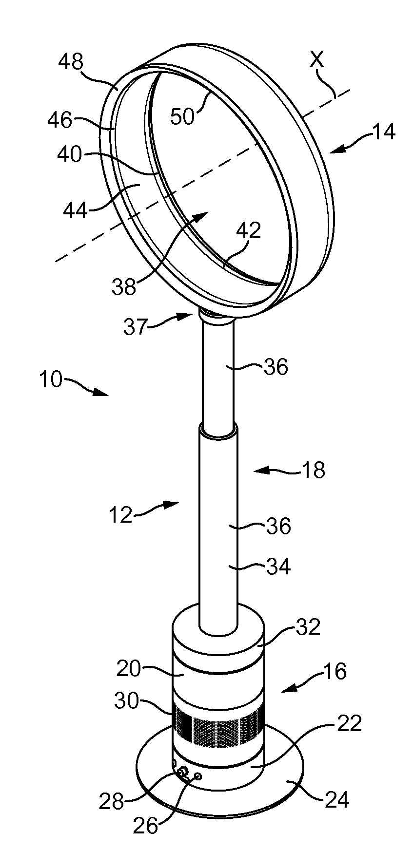
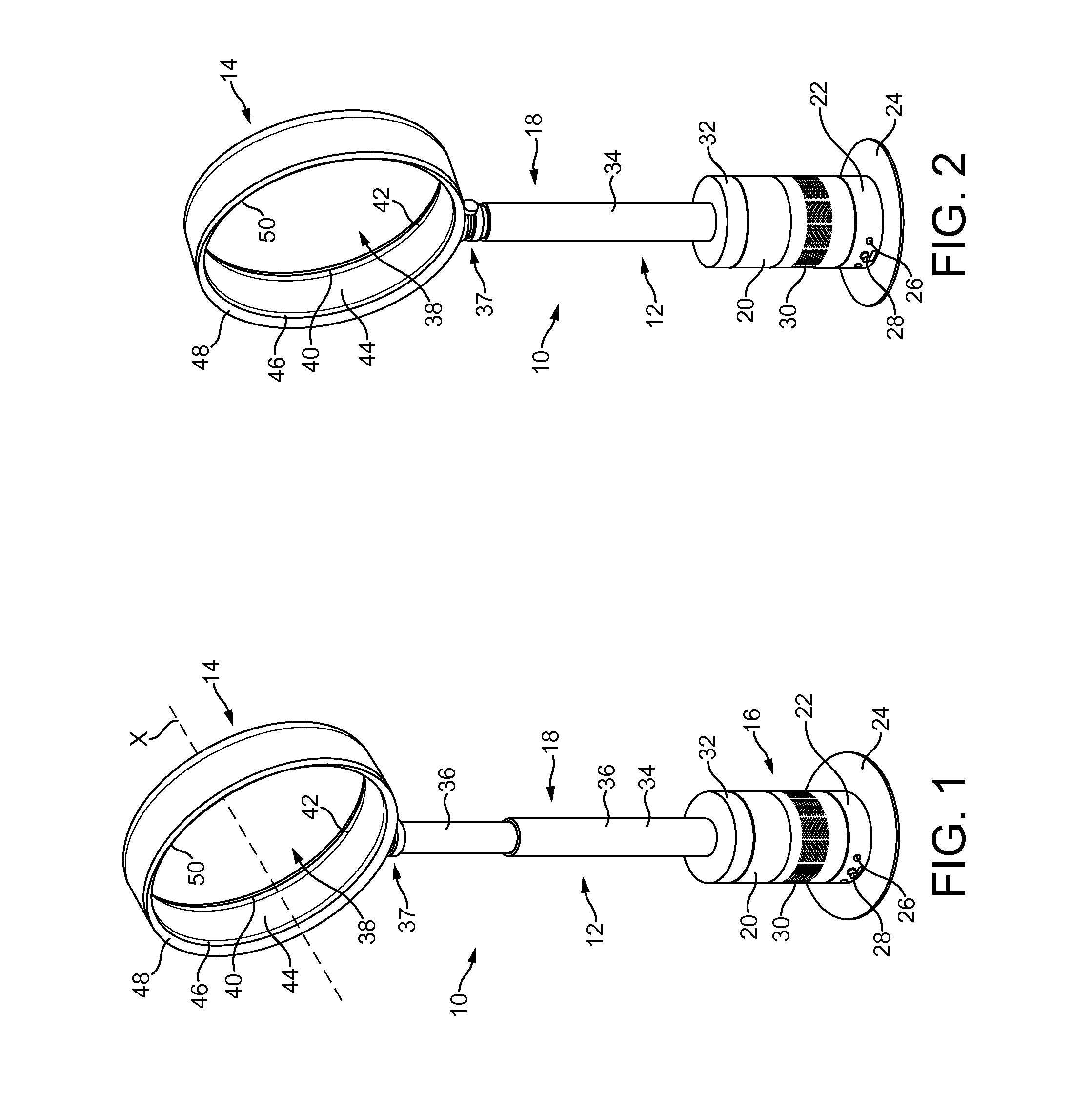
[0055]FIGS. 1 and 2 illustrate perspective views of an embodiment of a fan assembly 10. In this embodiment, the fan assembly 10 is a bladeless fan assembly, and is in the form of a domestic pedestal fan comprising a height adjustable pedestal 12 and an air outlet in the form of a nozzle 14 mounted on the pedestal 12 for emitting air from the fan assembly 10. The pedestal 12 comprises a base 16 and a telescopic duct 18 extending upwardly from the base 16 for conveying a primary air flow from the base 16 to the nozzle 14.

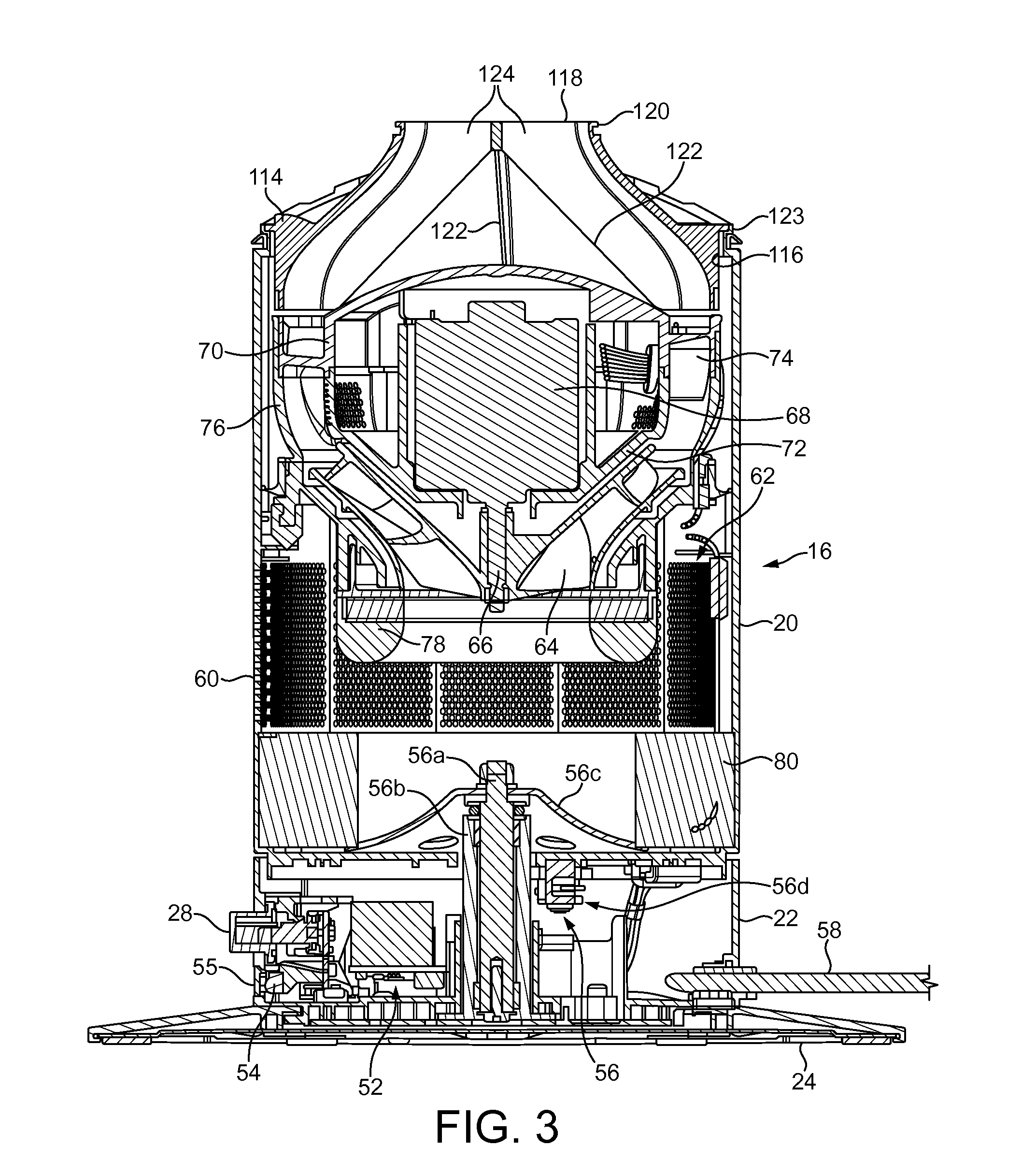
[0056]The base 16 of the pedestal 12 comprises a substantially cylindrical motor casing portion 20 mounted on a substantially cylindrical lower casing portion 22. The motor casing portion 20 and the lower casing portion 22 preferably have substantially the same external diameter so that the external surface of the motor casing portion 20 is substantially flush with the external surface of the lower casing portion 22. The lower casing portion 22 is mounted optionally o...


PUM


Abstract

A fan assembly for creating an air current includes an air inlet, an air outlet, an impeller, a motor for rotating the impeller to create an air flow passing from the air inlet to the air outlet, the air outlet comprising an interior passage for receiving the air flow and a mouth for emitting the air flow, the air outlet defining an opening through which air from outside the fan assembly is drawn by the air flow emitted from the mouth, a control circuit for controlling the motor, a remote control for transmitting control signals to the control circuit, and a plurality of magnets angularly spaced about the air outlet to provide a plurality of angularly spaced docking positions for the remote control on the air outlet.

Description

REFERENCE TO RELATED APPLICATIONS[0001]This application is a continuation of U.S. application Ser. No. 12 / 917,247, filed Nov. 1, 2010, which claims the priority of United Kingdom Application No. 0919473.9 filed Nov. 6, 2009, the entire contents of which are incorporated herein by reference.FIELD OF THE INVENTION[0002]The present invention relates to a fan assembly. In a preferred embodiment, the present invention relates to a domestic fan, such as a pedestal fan, for creating an air current in a room, office or other domestic environment.BACKGROUND OF THE INVENTION[0003]A conventional domestic fan typically includes a set of blades or vanes mounted for rotation about an axis, and drive apparatus for rotating the set of blades to generate an air flow. The movement and circulation of the air flow creates a ‘wind chill’ or breeze and, as a result, the user experiences a cooling effect as heat is dissipated through convection and evaporation.[0004]Such fans are available in a variety of...

Claims


Application Information

Patent Timeline
Patent Type & Authority Applications(United States)
IPC IPC(8): F04B49/00
CPCF04B49/00F04D25/08F04F5/16F04D27/00F04D25/06
Inventor GAMMACK, PETER DAVIDDYSON, JAMESSMITH, ARRAN GEORGEBROUGH, IAN JOHNTEYU, MON SHYMOHD.SALLEH, NOORHAZELINDA
Owner DYSON TECH LTD
Why Eureka
Try Eureka