Plate heat exchanger

a technology of heat exchanger and plate, which is applied in the direction of lighting and heating apparatus, washing machines, fastening devices, etc., can solve the problems reducing and long time, and achieves the effect of increasing the operational time of the plate heat exchanger

Inactive Publication Date: 2013-10-31
ALFA LAVAL CORP AB
View PDF11 Cites 15 Cited by
  • Summary
  • Abstract
  • Description
  • Claims
  • Application Information

AI Technical Summary

Benefits of technology

[0011]It is an object of the invention to at least partly overcome one or more of the above-identified limitations of

Problems solved by technology

However, in some cases opening and closing takes relatively long time which reduces the operational time of the plate heat exchanger, in particular if the plate heat exchanger must be regularly cleaned.
As a result, the plate heat exchanger may be more quickly opened and closed, which increases

Method used


Image

  • Plate heat exchanger
  • Plate heat exchanger
  • Plate heat exchanger

Examples


second embodiment

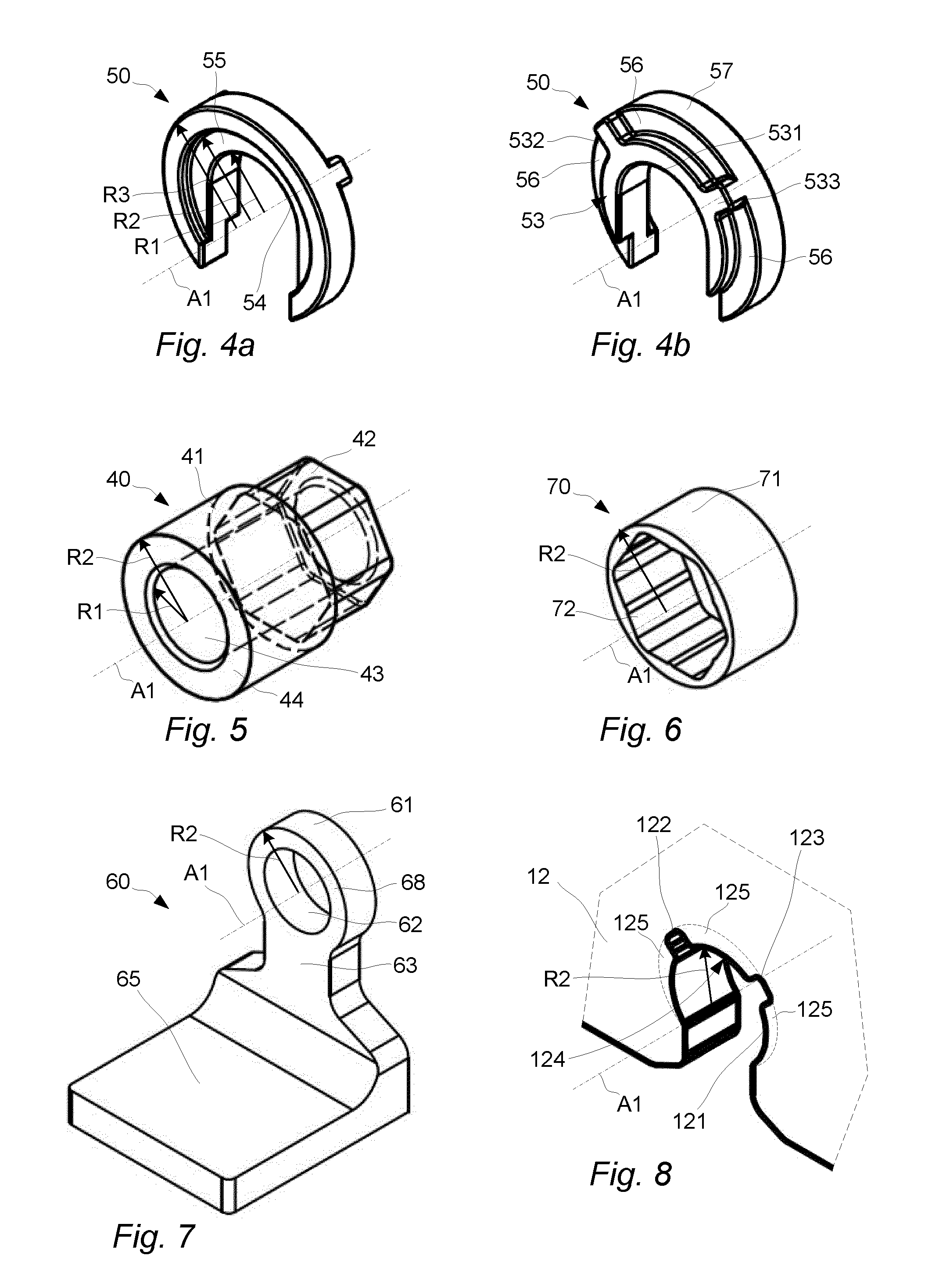
[0083]With reference to FIG. 13a a tightening member 412 is illustrated. In this embodiment the grip section of the tightening member 412 comprises a set of grooves 416 at an end of the tightening member 412. The tightening member 412 has also a guide section 422 with an outer periphery that is defined by the second radius R2.

third embodiment

[0084]With reference to FIG. 13b a tightening member 413 is illustrated. This embodiment corresponds to the embodiment of FIG. 13a with the difference that a grip section 417 is somewhat larger and is arranged as grooves at opposite sides of the tightening member 417. The tightening member 413 has a guide section 423 with an outer periphery that is defined by the second radius R2.

fourth embodiment

[0085]With reference to FIG. 13c a tightening member 414 is illustrated where a grip section 418 is arranged as elongated slots at a peripheral surface of the tightening member 414. The tightening member 414 has a guide section 424 with an outer periphery that is defined by the second radius R2. The guide section 424 is arranged intermediate the slots that form the grip section 418.


PUM

PropertyMeasurementUnit
Pressureaaaaaaaaaa
Shapeaaaaaaaaaa

Abstract

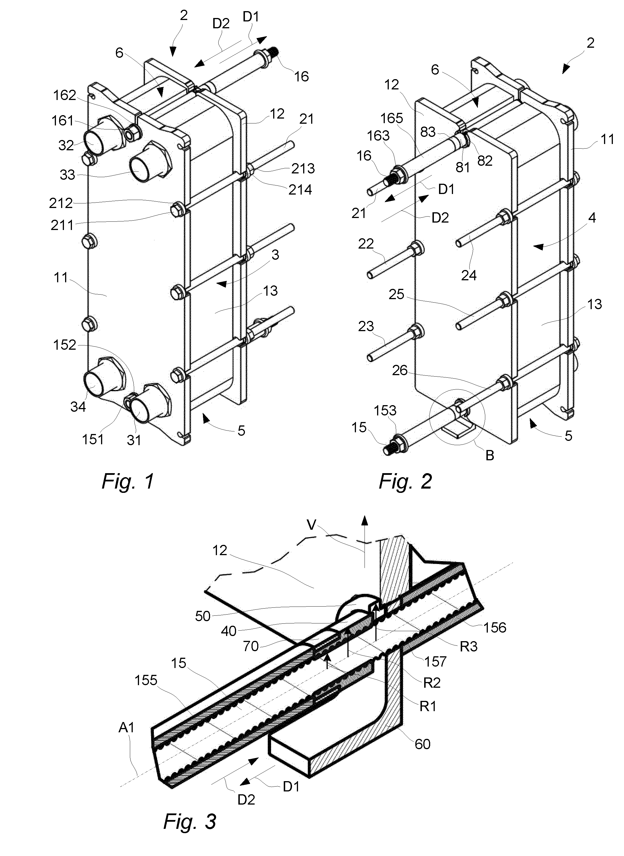
A plate heat exchanger comprising a set of heat exchanger plates arranged between a frame plate and a pressure plate. A guide bar guides the set of heat exchanger plates and the pressure plate relatively the frame plate, a tightening member is arranged on the guide bar and a plate engager is arranged intermediate the tightening member and the pressure plate for allowing the tightening member to press the pressure plate in a direction towards the frame plate. The plate engager is releasable and the tightening member is configured to protect the guide bar, such that the pressure plate may move in a direction from the frame plate and past the tightening member when the plate engager is released. A related method is also described.

Description

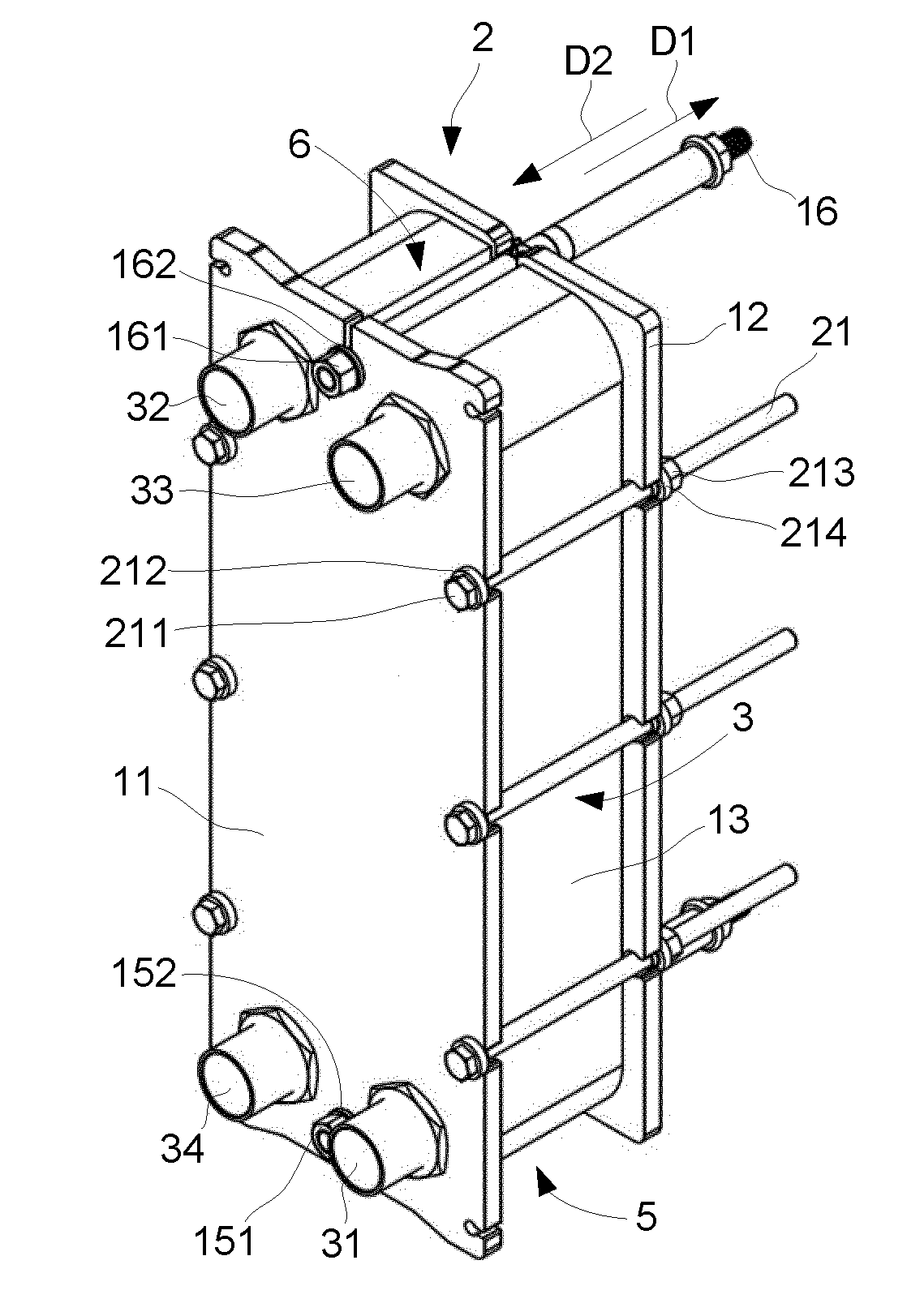
TECHNICAL FIELD[0001]The invention relates to a plate heat exchanger where a guide bar guides a set of heat exchanger plates and a pressure plate relatively a frame plate.BACKGROUND ART[0002]Plate heat exchangers are typically provided with a number of heat exchanger plates that are stacked between a frame plate and a pressure plate. Gaskets are often arranged between the heat exchanger plates, for example in applications where the plate heat exchanger should be opened for cleaning and maintenance of the heat exchanger plates, or when one or more heat exchanger plates should be replaced, added or removed.[0003]The heat exchanger plates are pressed together by tightening bolts that extend from the pressure plate to the frame plate. An arrangement of parallel flow channels that are sealed by the gaskets are formed between the heat exchanger plates for bringing two fluids at different temperatures thermally close to each other, which allows heat to be transferred from one of the fluids...

Claims


Application Information

Patent Timeline
IPC IPC(8): F28F3/08
CPCF28F3/083F16B43/00F16B43/005F28F9/007F28F9/0075Y10T29/49352
Inventor FORSTENIUS, CHRISTOPHERGIDNER, JOHAN
Owner ALFA LAVAL CORP AB
Why Eureka
Try Eureka