
Lateral field emission device

a field emission device and lateral field technology, applied in the direction of electric discharge tubes, discharge tubes/lamp details, discharge tubes cold cathodes, etc., can solve the problems of complicated processes and difficulty in integrating the field emission devi

Active Publication Date: 2013-10-31
KOREA UNIV RES & BUSINESS FOUND
View PDF4 Cites 4 Cited by
  • Summary
  • Abstract
  • Description
  • Claims
  • Application Information

AI Technical Summary

Benefits of technology

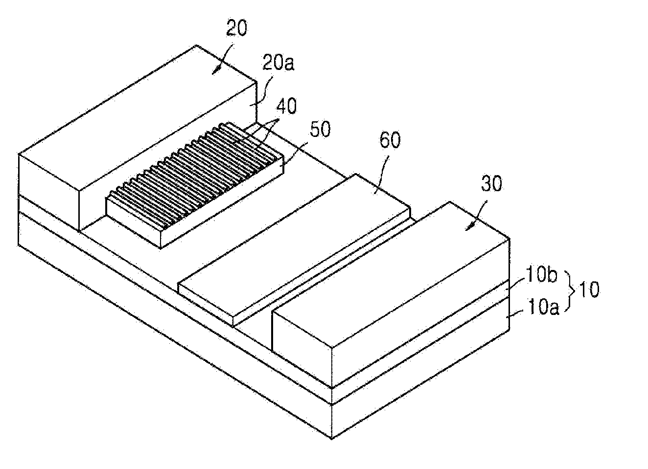
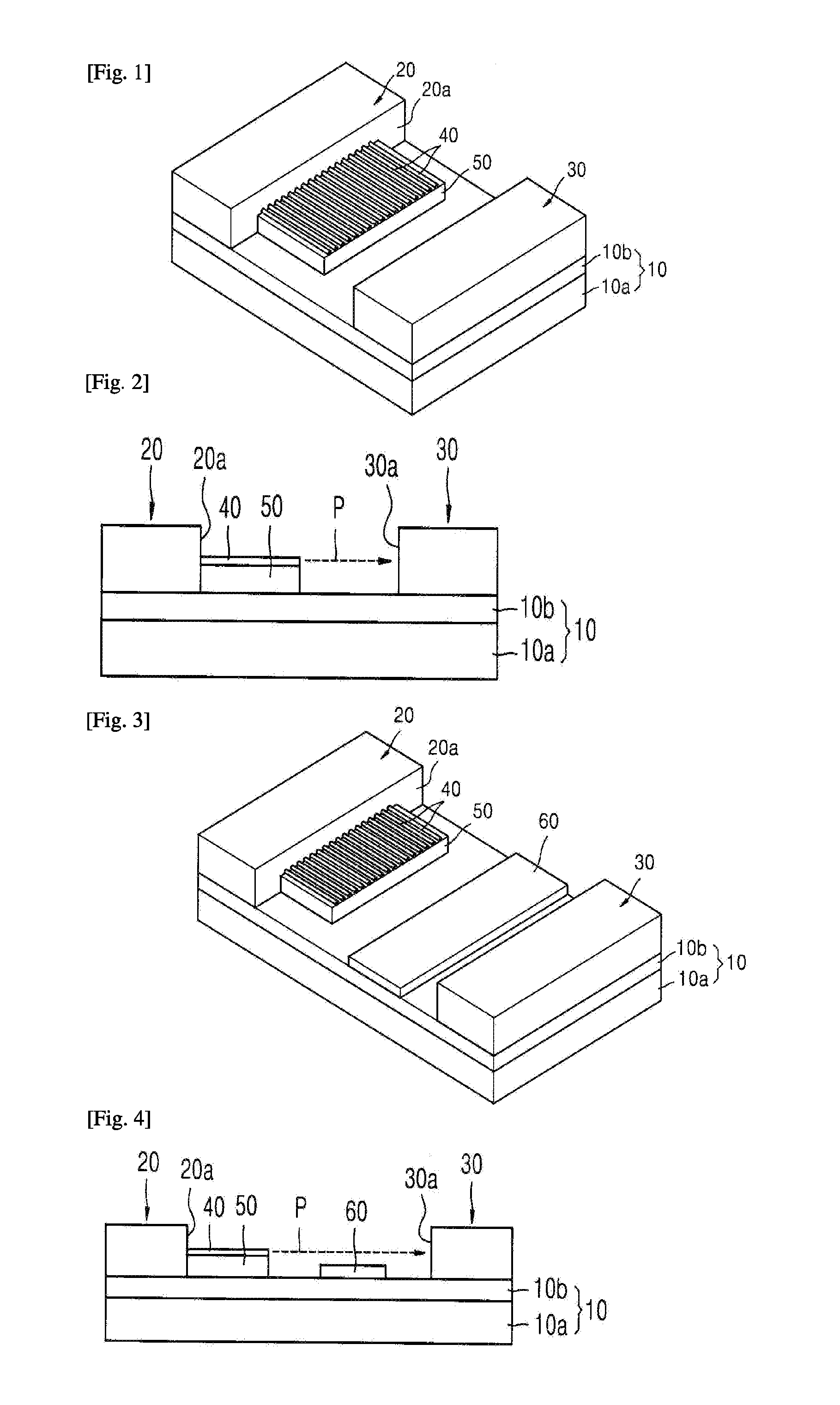
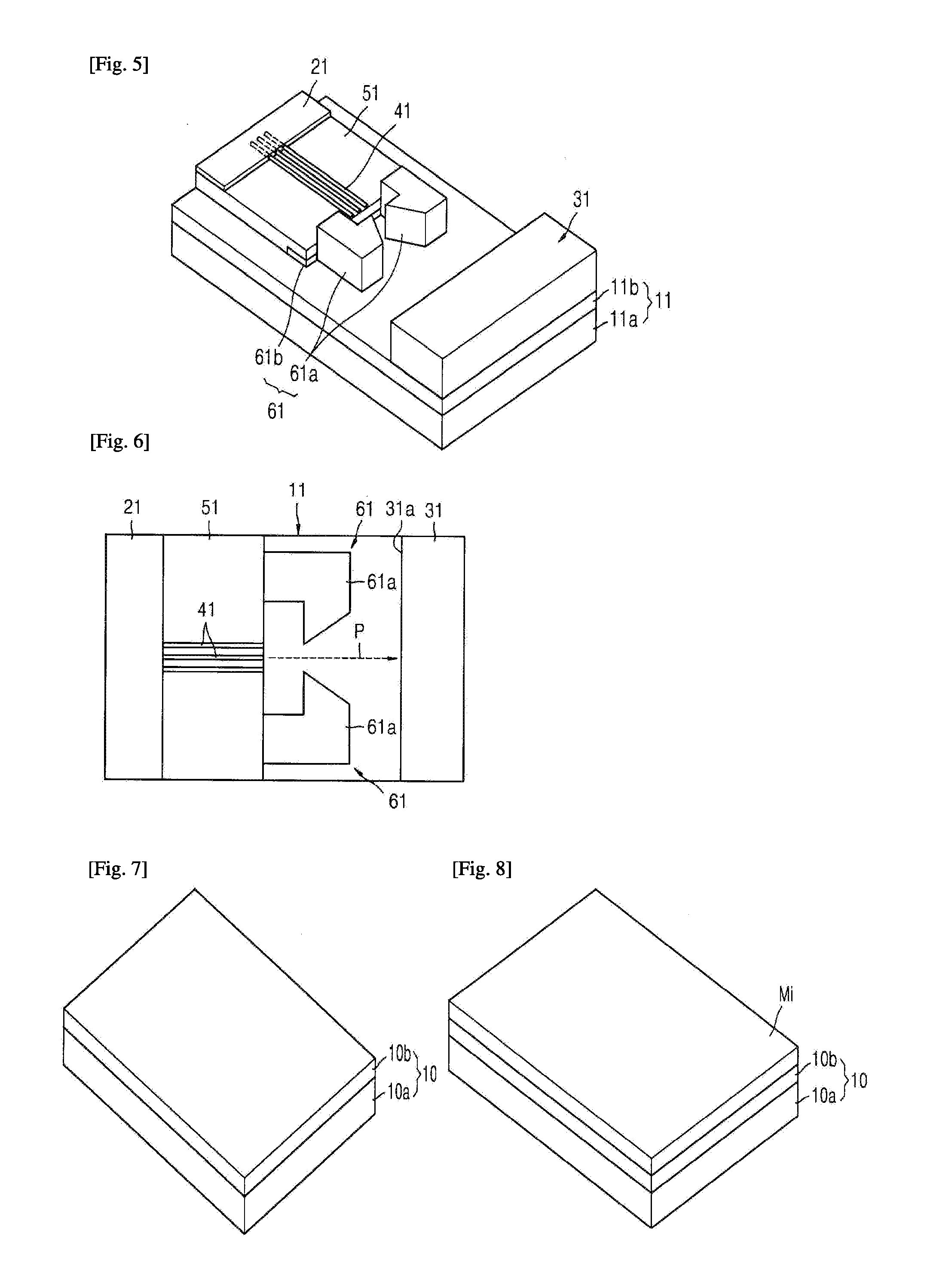
The present invention provides a lateral field emission device with a substrate, cathode, electron emission materials, supporting portion, cathode and anode structure, and optionally a gate. The device can have a conductive material of the same or different material as the electron emission materials, which can include carbon nano tubes, nano carbon materials, semiconductor nanowires, metal nanowires, carbon nanoplates, graphene, and graphene oxide. The device provides an efficient and reliable means for emitting electron beams in a controlled and directed manner.

Problems solved by technology

In order to form the spacer, complicate processes may be required.
Further, it may be difficult to integrate the field emission device due to the spacer.

Method used


Image

  • Lateral field emission device
  • Lateral field emission device
  • Lateral field emission device

Examples


Embodiment Construction

[0029]The invention is described more fully hereinafter with reference to the accompanying drawings, in which embodiments of the invention are shown. This invention may, however, be embodied in many different forms and should not be construed as limited to the embodiments set forth herein. Rather, these embodiments are provided so that this disclosure will be thorough and complete, and will fully convey the scope of the invention to those skilled in the art. In the drawings, the sizes and relative sizes of layers and regions may be exaggerated for clarity.

[0030]It will be understood that when an element or layer is referred to as being “on”, “connected to” or “coupled to” another element or layer, it can be directly on, connected or coupled to the other element or layer or intervening elements or layers may be present. In contrast, when an element is referred to as being “directly on,”“directly connected to” or “directly coupled to” another element or layer, there are no intervening...


PUM


Abstract

Described is a lateral field emission device emitting electrons in parallel with respect to a substrate. Electron emission materials having a predetermined thickness are arranged in a direction with respect to the substrate on a supporting portion. An anode is disposed on a side portion of the substrate, the anode corresponding to the electron emission materials.

Description

CROSS-REFERENCE TO RELATED APPLICATIONS[0001]This application claims priority under 35 USC §119 to Korean Patent Application No. 2011-2878 filed on Jan. 11, 2011, the contents of which are herein incorporated by reference in its entirety.BACKGROUND OF THE INVENTION[0002]1. Field of the Invention[0003]Example embodiments of the present invention relate to a lateral field emission device. More particularly, example embodiments of the present invention relate to a lateral field emission device of emitting electrons in parallel with respect to a substrate.[0004]2. Description of the Related Art[0005]Carbon nano tube (hereinafter, referred as to “CNT”), as an acicular electron emission material, has good characteristics of the electric, mechanical, chemical and thermal properties. Thus, CNT has been employed in a variety of applicable fields. CNT relatively has a low work function, a high aspect ratio and a nanosized end portion having a small radius of curvature such that CNT relatively...

Claims


Application Information

Patent Timeline
IPC IPC(8): H01J1/316
CPCH01J1/316B82Y20/00H01J2201/30446H01J2201/30469H01J1/30
Inventor LEE, CHEOL JINSHIN, DONG HOON
Owner KOREA UNIV RES & BUSINESS FOUND
Learn More