
Ink jet recording method, ultraviolet-ray curable ink, and ink jet recording apparatus

a recording method and ultraviolet-ray curable technology, applied in the field recording method, can solve the problems of image quality deterioration, small noise, and deterioration of the head members, and achieve good ejection stability and ejection amount stability of ultraviolet-ray curable ink. the effect of durability

Active Publication Date: 2013-10-31
SEIKO EPSON CORP
View PDF10 Cites 40 Cited by
  • Summary
  • Abstract
  • Description
  • Claims
  • Application Information

AI Technical Summary

Benefits of technology

The patent text describes the optimal temperature for ejecting ink from a printer head. By maintaining the temperature of the ejected ink at a relatively low level, the invention prevents deterioration of the printer head, improves durability, and ensures stable ejection and amount of ink. The optimal temperature range is between 28°C and 40°C, with a preferred range of 34°C to 40°C. The invention also recommends maintaining the viscosity of the ink at a low level, preferably 15 mPa·s or less, to ensure good ejection stability and amount of ink. These recommendations help to improve the performance and reliability of the printer.

Problems solved by technology

In addition, noise is small and thus the ink jet method is good as a recording method.
Among them, since the ultraviolet-ray curable ink of the nonsolvent system has a considerably higher viscosity than the aqueous ink of the solvent system, a viscosity fluctuation due to a temperature fluctuation during ejection is great, and this viscosity fluctuation exerts great influence on a variation in a droplet size and a variation in droplet ejection speed and further causes image quality deterioration.
However, the UV ink disclosed in JP-A-2003-200559 has a problem in that members of the head deteriorate due to the heating.
In addition, since the UV ink has a very high viscosity, if the ink is to be ejected without heating, ejection stability or ejection amount stability worsens.
However, according to the method, it has been found that a temperature of the ink tends to be fluctuated due to a variation in an environmental temperature, and ejection stability and ejection amount stability of the ink cannot be improved.
In addition, it has been found that the members of the head deteriorate due to a composition of the ultraviolet-ray curable ink with a very low viscosity, and thus durability of the head worsens, and, further, curing wrinkles tend to be generated.
However, according to the method, it has been found that a temperature of the ink tends to be fluctuated due to a variation in an environmental temperature, and ejection stability of the ink cannot be improved.
In addition, it has been found that the members of the head deteriorate due to a composition of the ultraviolet-ray curable ink with a very low viscosity, and thus durability of the head worsens, and, further, curing wrinkle tends to be generated.

Method used


Image

  • Ink jet recording method, ultraviolet-ray curable ink, and ink jet recording apparatus
  • Ink jet recording method, ultraviolet-ray curable ink, and ink jet recording apparatus
  • Ink jet recording method, ultraviolet-ray curable ink, and ink jet recording apparatus

Examples


examples

[0357]Hereinafter, the first embodiment will be described more in detail using Examples and Comparative Examples, but the invention is not limited to these Examples.

Materials Used

[0358]Materials used in Examples and Comparative Examples are as follows.

Polymerizable Compound

[0359]2-MTA (2-methoxyethyl acrylate; trade name, manufactured by OSAKA ORGANIC CHEMICAL INDUSTRY LTD.; a monofunctional (meth)acrylate)

[0360]4-HBA (4-hydroxybutyl acrylate; trade name, manufactured by OSAKA ORGANIC CHEMICAL INDUSTRY LTD.; a monofunctional (meth)acrylate)

[0361]VEEA (2-(2-vinyloxyethoxy)ethyl acrylate; trade name, manufactured by Nippon Shokubai Co., Ltd.; a monofunctional (meth)acrylate)

[0362]NEW FRONTIER PHE (phenoxyethyl acrylate; trade name, manufactured by Dai-ichi Kogyo Seiyaku Co., Ltd; a monofunctional (meth)acrylate; hereinafter, referred to as “PEA”)

[0363]V#160 (benzyl acrylate; trade name, manufactured by OSAKA ORGANIC CHEMICAL INDUSTRY LTD.; a monofunctional (meth)acrylate; hereinafter,...

examples 1 to 13

and Comparative Examples 2, 4, 5 and 9

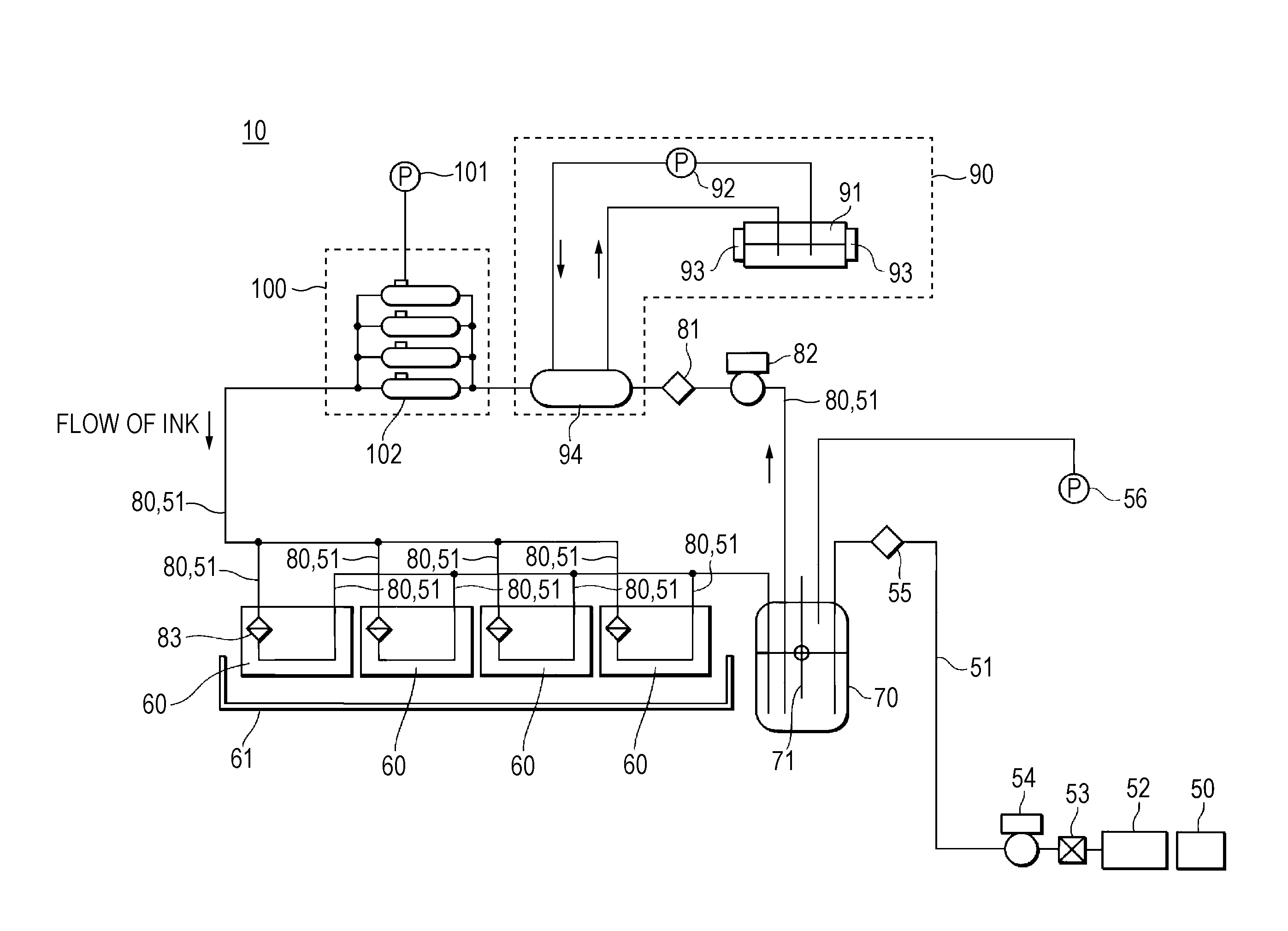
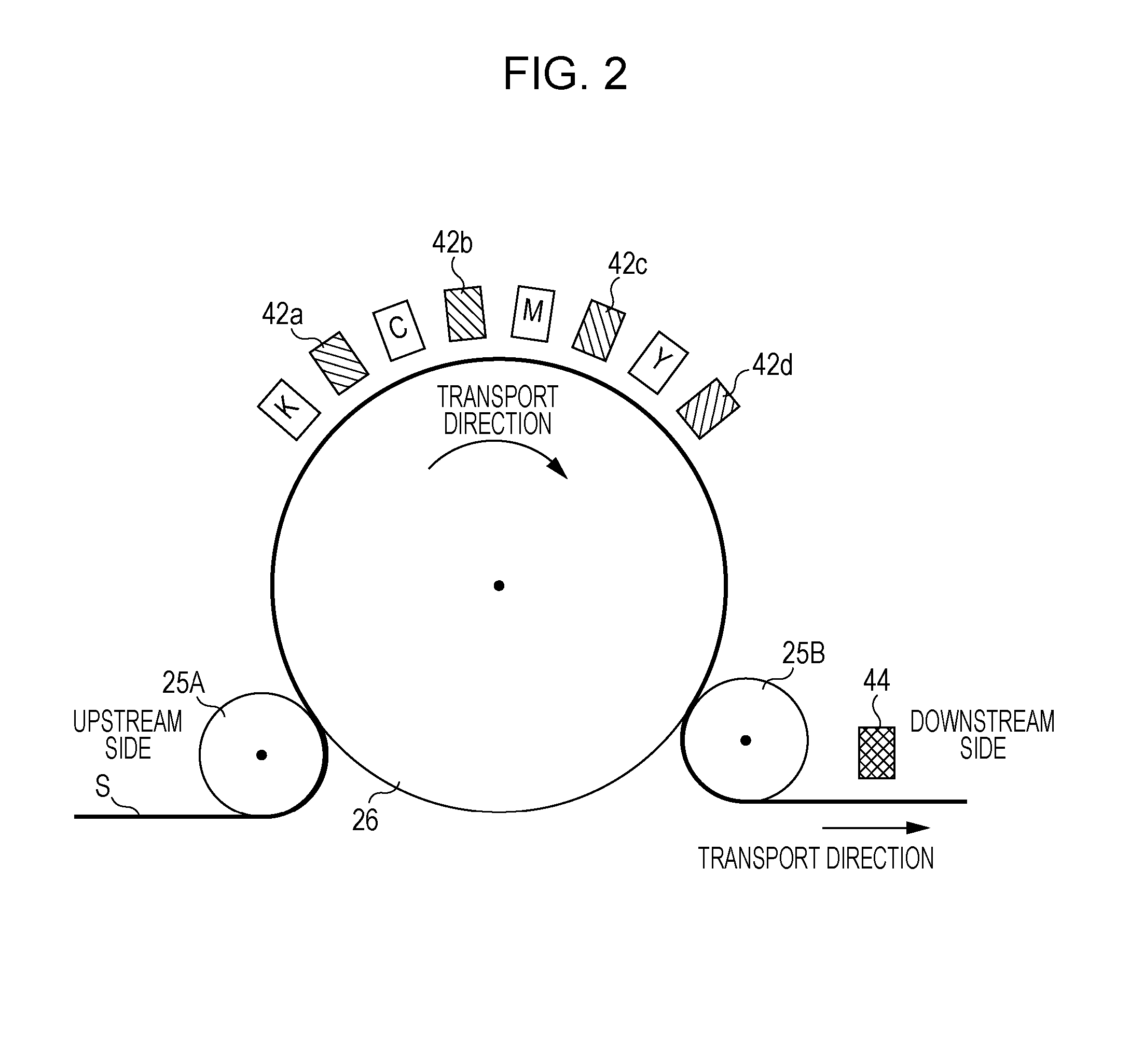
[0382]The line printer shown in FIG. 2 provided with the ink supply device shown in FIG. 3 was used in which four line heads having a length substantially equal to a width (recording width) of a recording surface, on which an image is to be recorded, were arranged in parallel in the width direction. The nozzle density of the heads was 600 dpi.

[0383]A heating temperature of the heater provided in the ink circulating device was adjusted for each Example and Comparative Example such that a temperature (ejection temperature) of an ejected ink became the temperature shown in Tables 2 to 4 on the basis of a temperature of the nozzle plate measured in the thermocouple provided in the nozzle plate of the head, it was checked that an average temperature became each temperature of Examples and Comparative Examples by measuring a temperature every five minutes while the ink was continuously ejected from the head for sixty minutes, and the average temperatu...

example 17

[0389]Recording was performed in the same manner as in above-described Examples 1 and the like except that the heating device in the circulation path was turned off, and, instead, a heater was mounted in the head, and the ink temperature became 33° C. by heating the head.

[0390]In addition, in relation to the heater of the head, as shown in FIG. 2 of JP-A-2003-200559, the heater was installed in the head, and the head including the reservoir was heated.


PUM


Abstract

An ink jet recording method includes ejecting an ultraviolet-ray curable ink of which a viscosity at 28° C. is 8 mPa·s or more from a head to a recording medium, and curing the ultraviolet-ray curable ink attached to the recording medium, wherein, in the ejecting of the ultraviolet-ray curable ink, the ultraviolet-ray curable ink is heated such that a temperature of the ejected ultraviolet-ray curable ink becomes 28° C. to 40° C., and a viscosity of the ultraviolet-ray curable ink at the temperature is 15 mPa·s or less.

Description

CROSS REFERENCES TO RELATED APPLICATIONS[0001]The entire disclosure of Japanese Patent Application No. 2012-99995, filed Apr. 25, 2012 and 2012-249034, filed Nov. 13, 2012 and 2012-102537, filed Apr. 27, 2012 and 2012-250030, filed Nov. 14, 2012 are expressly incorporated by reference herein.BACKGROUND[0002]1. Technical Field[0003]The present invention relates to an ink jet recording method, an ultraviolet-ray curable ink, and an ink jet recording apparatus.[0004]2. Related Art[0005]In the related art, various methods are used as a recording method of forming an image on a recording medium such as paper on the basis of an image data signal. Among them, since an ink jet method of ejecting an ink onto only a necessary image part with low-priced apparatus and directly forming an image on a recording medium, an ink can be used with high efficiency and thus running costs are low. In addition, noise is small and thus the ink jet method is good as a recording method.[0006]In recent years, ...

Claims


Application Information

Patent Timeline
IPC IPC(8): B41J11/00
CPCB41J11/002B41M7/0081B41J11/00214B41J2/17509B41J2/2107
Inventor KOBAYASHI, YOSHIHIROMIZUTAKI, YUSUKEKUMAGAI, TOSHIOANDO, MASAAKIKIDA, HIROAKIKOIKE, KAORUYOSHIZAWA, MITSUAKI
Owner SEIKO EPSON CORP
Learn More