
Method and Apparatus for Selective Seismic Detection of Elongated Targets

a technology of elongated targets and methods, applied in the field of selective seismic detection of elongated targets, can solve the problems of difficult generating high-frequency (short wavelength), ineffective conventional seismic reflection techniques employing one or more detector lines and using compressional (p) wave sources located at positions distributed along the detector line, and inability to detect slender one-dimensional targets such as underground pipes

Inactive Publication Date: 2013-10-31
OWEN THOMAS E
View PDF7 Cites 8 Cited by
  • Summary
  • Abstract
  • Description
  • Claims
  • Application Information

AI Technical Summary

Benefits of technology

The patent text describes a method for detecting and mapping underground pipes using seismic reflection techniques. The technical effects of this patent include improved detection of slender targets such as pipes in shallow unconsolidated soil media using a closely spaced source and sensor transducer system to produce localized near-vertical short-path illumination and to receive relatively short-path near-vertical reflections from the subsurface target. The use of short wavelengths offers advantages such as shorter attenuation and refraction effects in soil materials. The patent also discusses the use of small, wide-bandwidth vibrator sources for surveys and the importance of off-line data processing. The invention aims to overcome limitations related to the need for short wavelengths, difficultly in generating high-frequency source signals, and masking of weak reflections from underground targets.

Problems solved by technology

Conventional seismic reflection techniques employing one or more line of detectors and using a compressional (P) wave source located at positions distributed along the detector line are not particularly effective in detecting slender one-dimensional targets such as underground pipes in shallow unconsolidated soil media.
The primary limitations are related to: (1) the important need for short wavelength target illumination comparable with the diameter of pipe targets of interest to obtain useful reflection signals; (2) the difficulty of generating high-frequency (short wavelength) seismic source signals using conventional P-wave sources; (3) the detrimental effect of anelastic absorption of such short wavelengths in soil materials; (4) off-vertical refraction effects caused by positive velocity gradients with depth in shallow unconsolidated soils; (5) the reflection coefficient of cylindrically shaped targets such as a pipe which contains an inherent partition of reflected energy in the form of P wave conversion to shear (S) waves when the incident wave is generated by a compressional wave source; and (6) the need for off-line data processing.
While these sources have solved the important need for generating high-resolution source signals for detecting underground pipes, the basic methods relevant to pipe detection are limited by two critical factors: (1) attenuation of high-frequency seismic signals in unconsolidated soils; and (2) masking of weak reflections from underground targets by seismic wave energy transmitted directly from the surface-based source to the nearby surface-based sensor.
Therefore, attenuation tends to reduce the strength of the desired short wavelength reflections from pipe targets more severely than the undesired lower frequency reflections from larger anomalies in the vicinity of the pipe.
As a consequence, seismic reflections from pipe targets are usually weak and may be near the threshold of detection using state-of-the-art instrumentation.
The second factor above is a self-interference effect inherent in most seismic exploration systems and, in conventional practice, cannot be completely avoided.
This interference is caused by the close proximity of the source and sensor transducers and direct transmission of the locally strong source signals over the short path between the source and sensor.
Such strong direct-arriving signals can mask the weak pipe reflections of interest and can overdrive the receiving system, preventing its operation at the desired high-sensitivity needed to reveal otherwise threshold detectable signals.

Method used


Image

  • Method and Apparatus for Selective Seismic Detection of Elongated Targets
  • Method and Apparatus for Selective Seismic Detection of Elongated Targets
  • Method and Apparatus for Selective Seismic Detection of Elongated Targets

Examples


Embodiment Construction

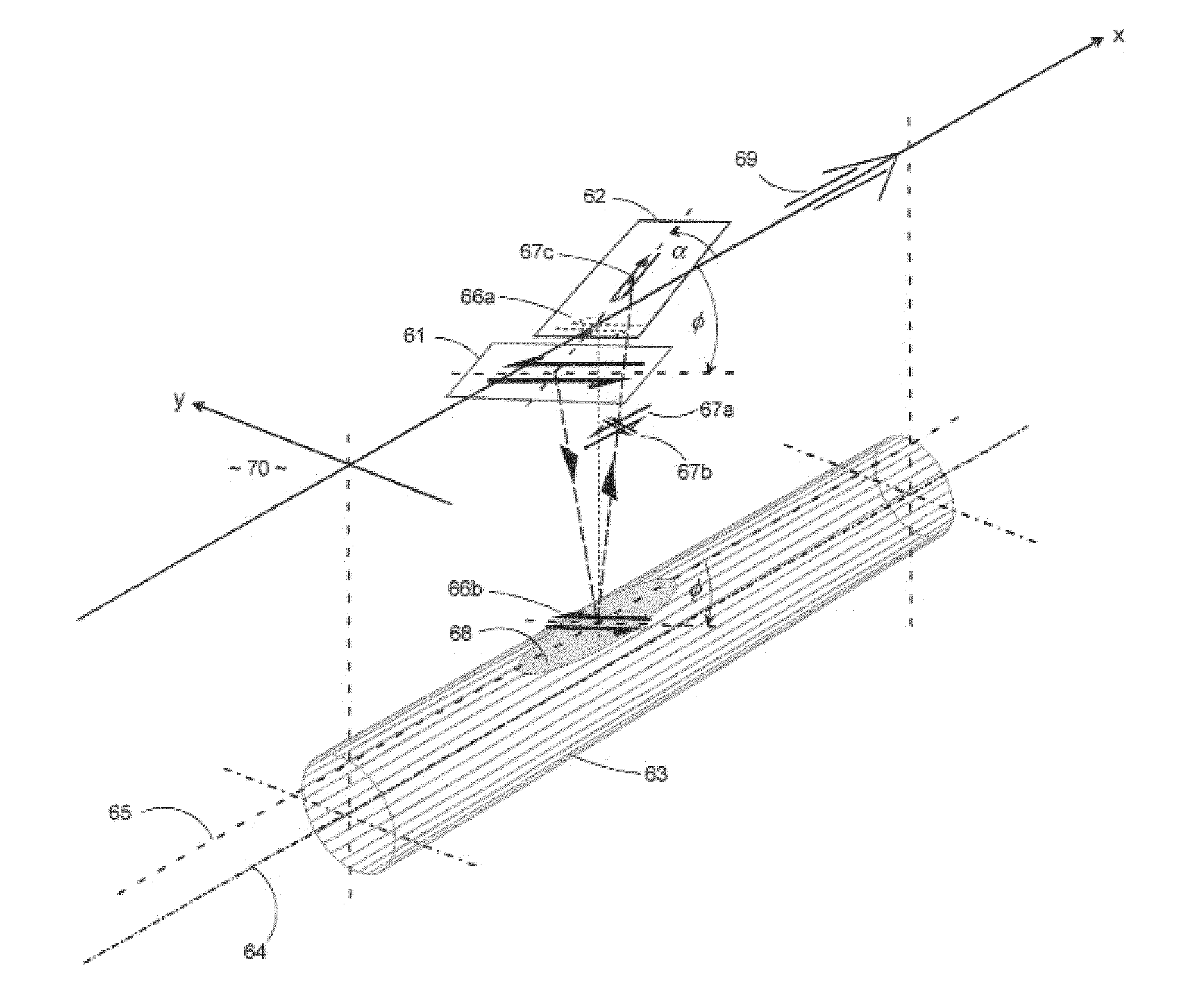
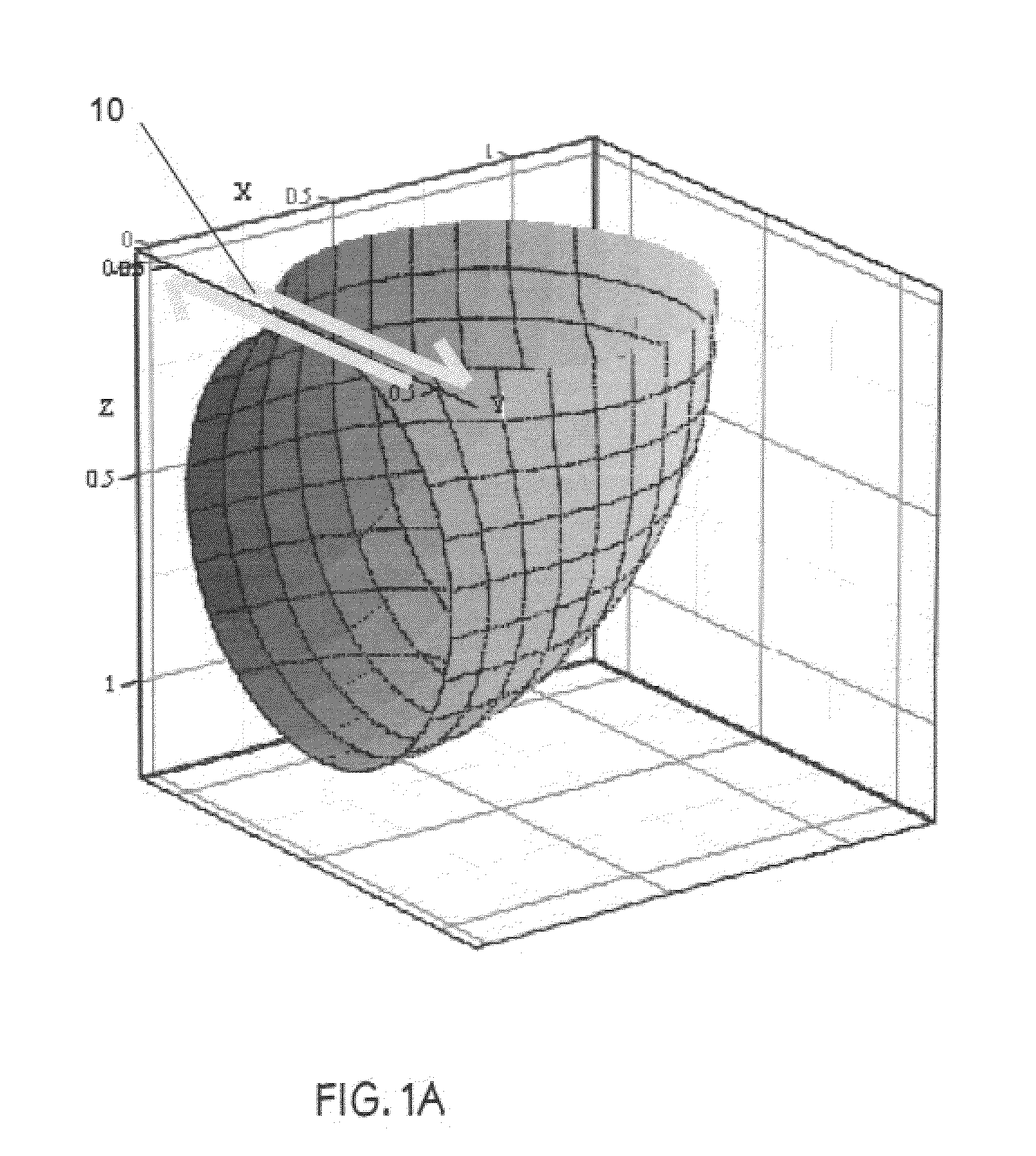
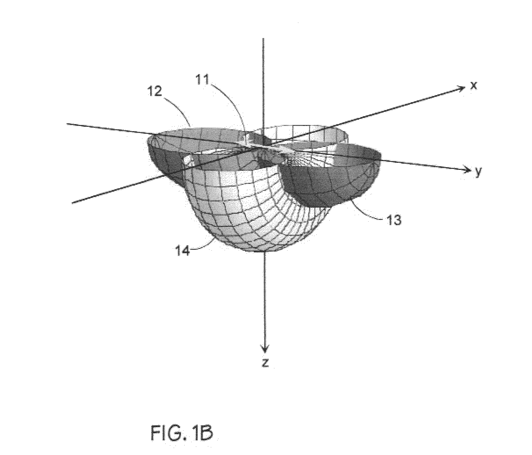
[0027]The invention disclosed herein refers to a high-resolution seismic reflection technique utilizing horizontally polarized shear (SH) wave source and sensor transducers to provide operating features and functions for selectively detecting and mapping elongate cylindrical targets such as shallow underground pipes or conduits. The principal features and functions exemplified by this invention are:

[0028](1) A seismic vibrator source capable of generating SH waves in the frequency range 50-2,000 Hz when coupled to ground surfaces such as soil or paved surfaces overlying soil; the soil being the host medium potentially containing one or more underground utility pipes or conduits;

[0029](2) A seismic sensor capable of detecting SH waves when coupled to ground surfaces such as soil or paved surfaces overlying soil; the soil being the host medium potentially containing one or more underground utility pipes or conduits;

[0030](3) The SH-wave source and SH-wave sensor in (1) and (2) arrange...


PUM


Abstract

A seismic wave source and sensing system coupled to the surface of an elastic wave propagation medium has a seismic wave source transducer having a preferred axis of vibration oriented horizontally on the surface of the elastic wave propagation medium. A seismic wave sensing transducer has a preferred axis of vibration response oriented horizontally on the surface of said elastic wave propagation medium such that said sensing transducer is capable of detecting dynamic particle motions and displacements of SH waves. An arrangement of the source and sensing transducers is provided on the surface of the elastic wave propagation medium. A recording system capable of acquiring and storing reflected SH wave signals detected by the sensing transducer, wherein the recorded signals represent reflections from contrasting physical properties within the elastic wave propagation medium to provide preferential detection of elongate subsurface targets such as utility pipes, conduits, and other similar object.

Description

[0001]This application claims priority to U.S. Provisional Patent Application Ser. No. 61 / 640,088 filed 30 Apr. 2012, which is incorporated herein by reference for all purposes.BACKGROUND OF INVENTION[0002]Conventional seismic reflection techniques employing one or more line of detectors and using a compressional (P) wave source located at positions distributed along the detector line are not particularly effective in detecting slender one-dimensional targets such as underground pipes in shallow unconsolidated soil media. The primary limitations are related to: (1) the important need for short wavelength target illumination comparable with the diameter of pipe targets of interest to obtain useful reflection signals; (2) the difficulty of generating high-frequency (short wavelength) seismic source signals using conventional P-wave sources; (3) the detrimental effect of anelastic absorption of such short wavelengths in soil materials; (4) off-vertical refraction effects caused by posi...

Claims


Application Information

Patent Timeline
IPC IPC(8): G01V1/28
CPCG01V1/284
Inventor OWEN, THOMAS E.
Owner OWEN THOMAS E
Learn More