Turbine diaphragm construction

a technology for turbines and diaphragms, which is applied in the direction of machines/engines, stators, liquid fuel engines, etc., can solve the problems of metallurgical defects, cost of welding together the components of the diaphragm, etc., and achieve the effect of accurate manufacturing and avoiding excessive aerodynamic drag penalties

Active Publication Date: 2013-10-31
GENERAL ELECTRIC TECH GMBH
View PDF5 Cites 8 Cited by
  • Summary
  • Abstract
  • Description
  • Claims
  • Application Information

AI Technical Summary

Benefits of technology

[0017]To maintain aerodynamic smoothness, confronting ends of the radially inner elongate platform portions should preferably butt up to each other when inserted into the blade unit retaining feature of the inner ring, such that the platform portions extend continuously around the inner port wall of the diaphragm in the circumferential direction.
[0018]Clearly, with regard to their dimensions and surface finishes, the platform portions of the blade units and the blade retaining features of the inner and outer rings should be accurately manufactured and closely matched to each other, so that the inner and outer port walls of the diaphragm are sufficiently smooth to avoid excessive aerodynamic drag penalties.

Problems solved by technology

Since such rings in large turbines have substantial dimensions in the axial and radial directions of the turbine, e.g., 100 mm to 200 mm, the cost of welding together the components of the diaphragm is a significant factor in the ex-works price of a large steam turbine, not least because the necessary deep penetration welds require advanced specialist welding equipment for their production.
Furthermore, welds are a possible source of metallurgical defects in the diaphragm and it is also necessary to heat treat the diaphragm in order to relieve stresses in the diaphragm caused by the welding processes.

Method used


Image

  • Turbine diaphragm construction
  • Turbine diaphragm construction
  • Turbine diaphragm construction

Examples


Embodiment Construction

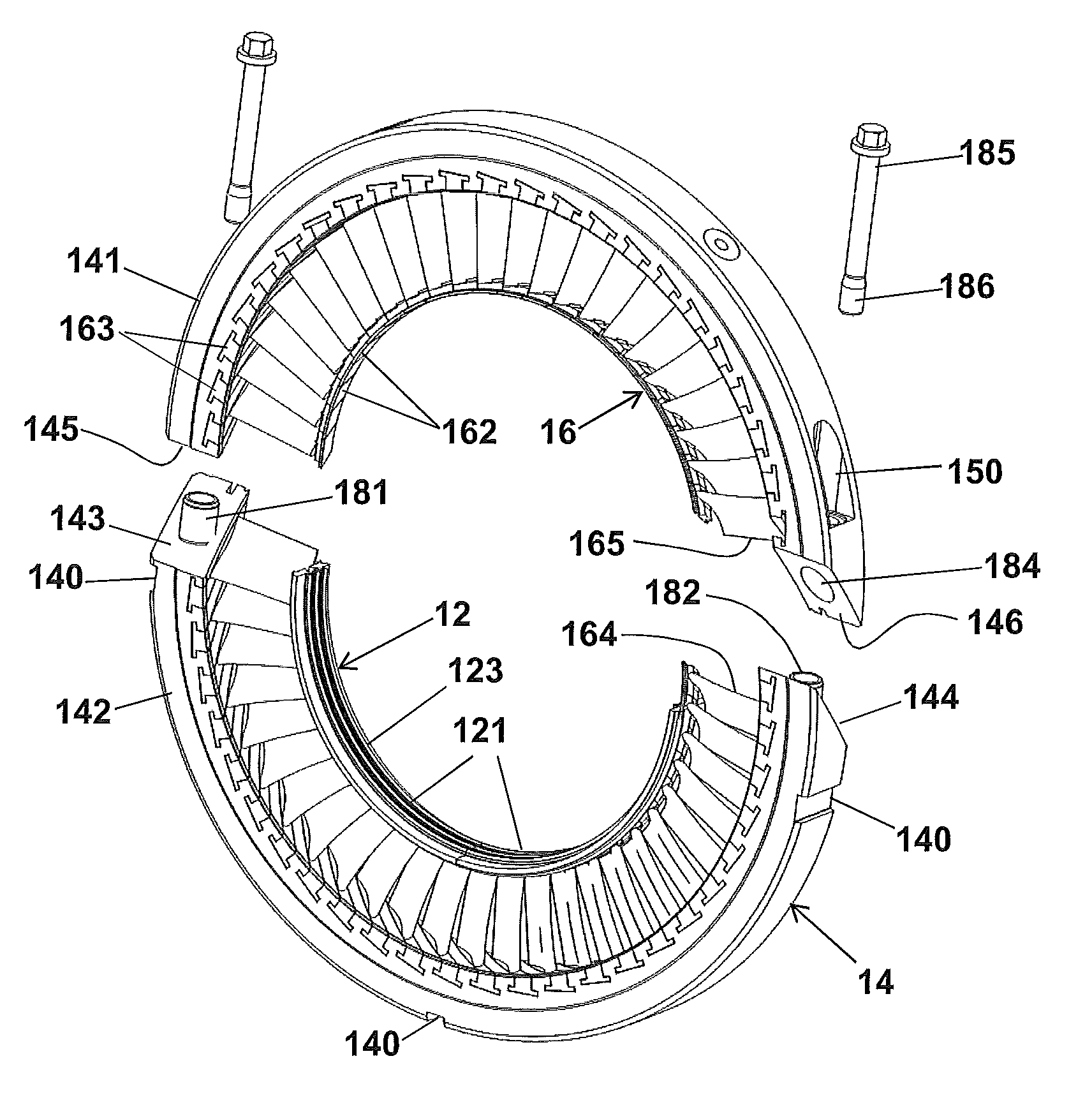
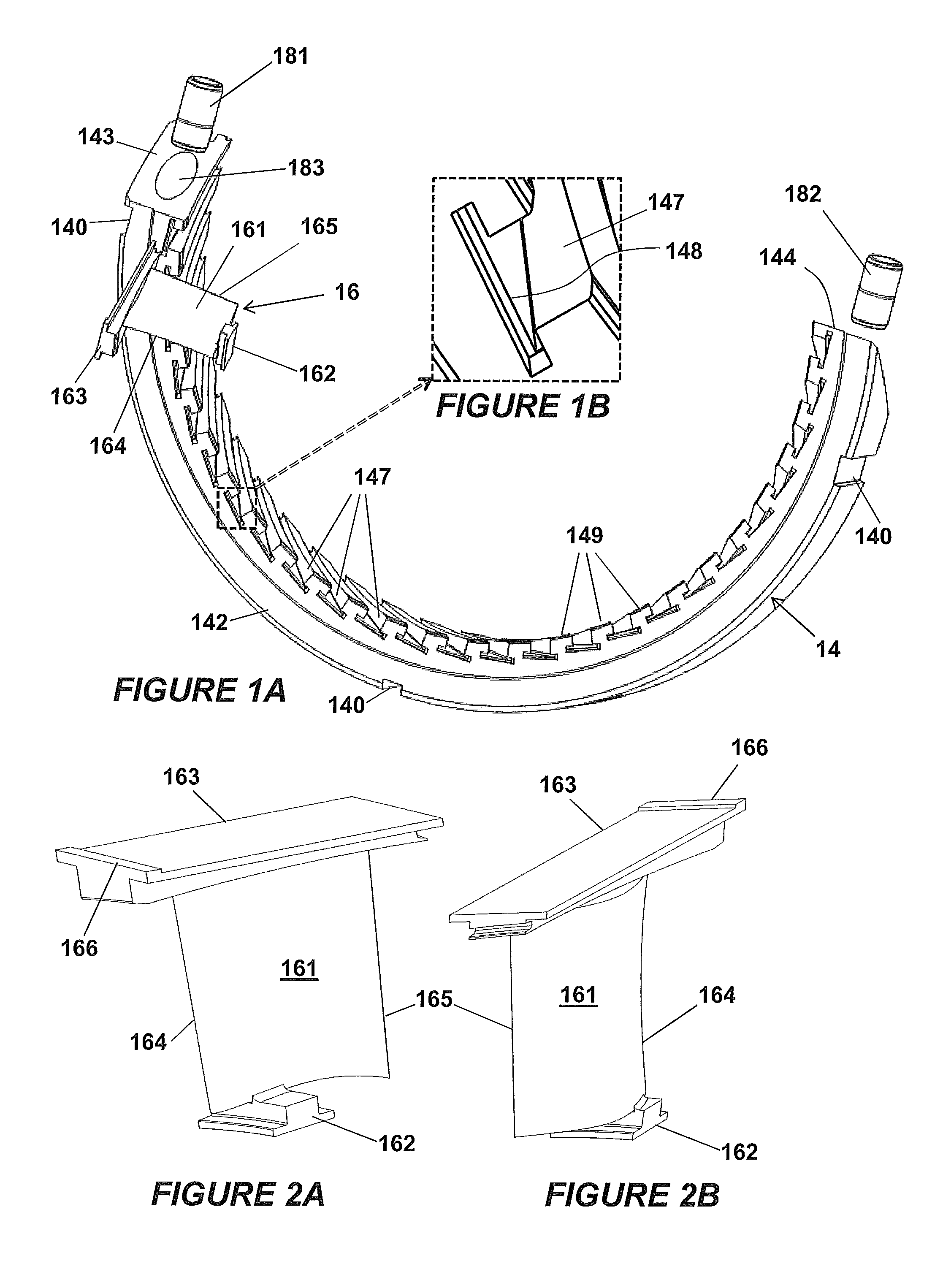
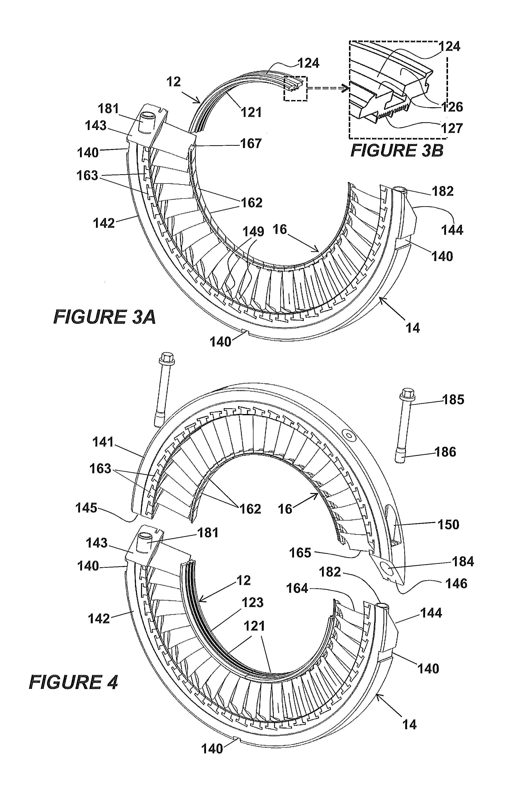
[0033]Steam turbine diaphragms are normally constructed by welding their components together, but in accordance with the present concept, FIGS. 1A, 3A, 4 and 5 show a high pressure steam turbine diaphragm 10 and which is constructed without welding or other fusion or adhesive metal joining techniques. Referring first to FIG. 5, which shows the diaphragm after it has been assembled having a major axis X-X, the diaphragm 10 comprises a radially inner diaphragm ring 12, a radially outer diaphragm ring 14 and an annular array of static blade units 16 arranged between the inner and outer rings. The illustrated embodiment is a diaphragm with a radially compact type of construction, which has a much reduced radial thickness of its inner diaphragm ring 12 compared with the more robust type of construction traditionally used for large steam turbines. In fact, as will be apparent from the description below, the inner diaphragm ring 12 of the illustrated embodiment is effectively part of all t...


PUM

PropertyMeasurementUnit
stagger angleaaaaaaaaaa
shapeaaaaaaaaaa
circumferenceaaaaaaaaaa

Abstract

An axial flow turbine diaphragm is constructed without welding or other metal fusion or melting techniques. Static blade units are attached to inner and outer diaphragm rings by radially inner platform portions that engage the radially inner ring, and radially outer platform portion s that engage the radially outer ring, the inner platform portions being elongate in the circumferential direction of the turbine diaphragm and the outer platform portions being elongate in a direction compatible with the stagger angle of the aerofoils. The outer circumference of the radially inner ring has a blade unit retaining feature of complementary shape and orientation to the inner platform portions of the static blade units, and the inner circumference of the radially outer ring is provided with a plurality of blade unit retaining features of complementary shape and orientation to corresponding outer platform portions of the static blade units.

Description

TECHNICAL FIELD[0001]This disclosure relates to the construction of diaphragms for turbines, and in particular, to a novel structure and assembly process for diaphragms in axial flow steam turbines.TECHNICAL BACKGROUND[0002]A known way of constructing a steam turbine diaphragm is to mount an annulus of static guide blades between an inner ring and an outer ring. Each such blade comprises a blade unit in which an aerofoil portion extends between an inner platform and an outer platform, the blade unit being machined as a single component. This is known as the “platform” type of construction. Each platform is in the form of a segment of a cylinder so that when the annulus of blade units is assembled, the inner platforms combine to create an inner port wall and the outer platforms combine to create an outer port wall. The inner platforms are welded to an inner ring that retains the turbine blades and provides a mount for a sealing arrangement, such as a labyrinth seal, that acts between...

Claims


Application Information

Patent Timeline
Patent Type & Authority Applications(United States)
IPC IPC(8): F01D9/04
CPCF01D9/042F01D25/246Y10T29/49236F05D2240/80F05D2250/314F05D2220/31
Inventor BRUMMITT-BROWN, ANGUS ROBERTMISTRY, KANULORD, ADRIAN CLIFFORD
Owner GENERAL ELECTRIC TECH GMBH
Why Eureka
Try Eureka