Fuel Cell System, Use Of A Fuel Cell System And Aircraft With A Fuel Cell System

a fuel cell and system technology, applied in the field of fuel cell systems, can solve the problems of difficult operation, high involvement of monitoring the fuel line over its entire length, etc., and achieve the effect of reducing the flushing of the housing

Active Publication Date: 2013-10-31
AIRBUS OPERATIONS GMBH
View PDF7 Cites 15 Cited by
  • Summary
  • Abstract
  • Description
  • Claims
  • Application Information

AI Technical Summary

Benefits of technology

[0020]In an advantageous embodiment of the invention, air from the surroundings is used as an oxygen source and is conveyed to the cathode of the fuel cell. By using the oxygen content in the ambient air, strongly oxygen-depleted air arises which, after possible condensing-out of the arising process water, is then transported to the exhaust gas line so that a combustible hydrogen-air mixture can be prevented from arising. In an exception from the above, a certain component of the exhaust gas can be used to render inert a fuel tank of a vehicle, a cargo compartment of a vehicle, or other zones of a higher-level system, for example an avionics compartment of an aircraft. To this effect, prior condensing-out of the water and subsequent drying are required.
[0021]In a further advantageous embodiment of the invention, in addition a fan is arranged in the housing in order to reinforce flushing of the housing. With the use of the fuel cell system according to the invention in an aircraft, in particular during time on the ground such a fan is advantageous because as a result of the absence of a pressure differential between the interior of the housing and the surroundings of the aircraft there is no suction effect on the exhaust gas line and consequently passive flushing by way of a nozzle may not be adequately effective.

Problems solved by technology

Providing a single supply line for fuel cell fuel and its constant monitoring for correct functioning can present a challenge, in particular in complex higher-level systems, for example in vehicles, and in particular in aircraft.
Furthermore, monitoring a fuel line over its entire length is very involved and requires at least several sensors that are designed to be able to detect an unusual hydrogen concentration.

Method used


Image

  • Fuel Cell System, Use Of A Fuel Cell System And Aircraft With A Fuel Cell System
  • Fuel Cell System, Use Of A Fuel Cell System And Aircraft With A Fuel Cell System
  • Fuel Cell System, Use Of A Fuel Cell System And Aircraft With A Fuel Cell System

Examples


Embodiment Construction

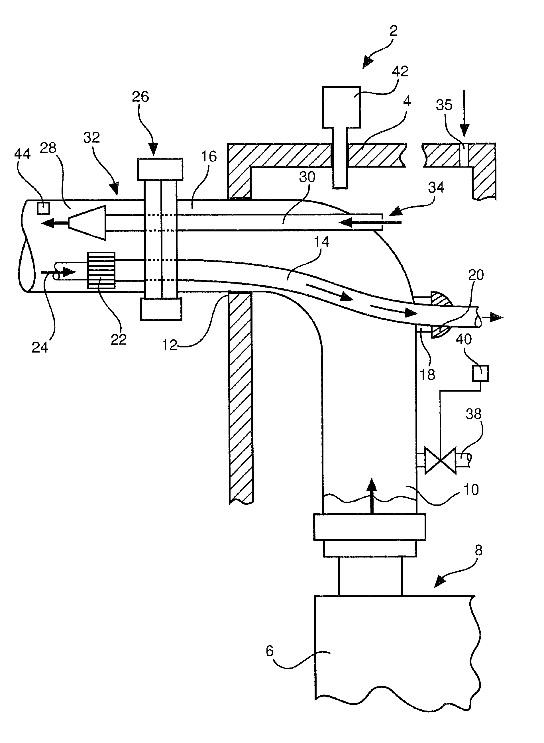
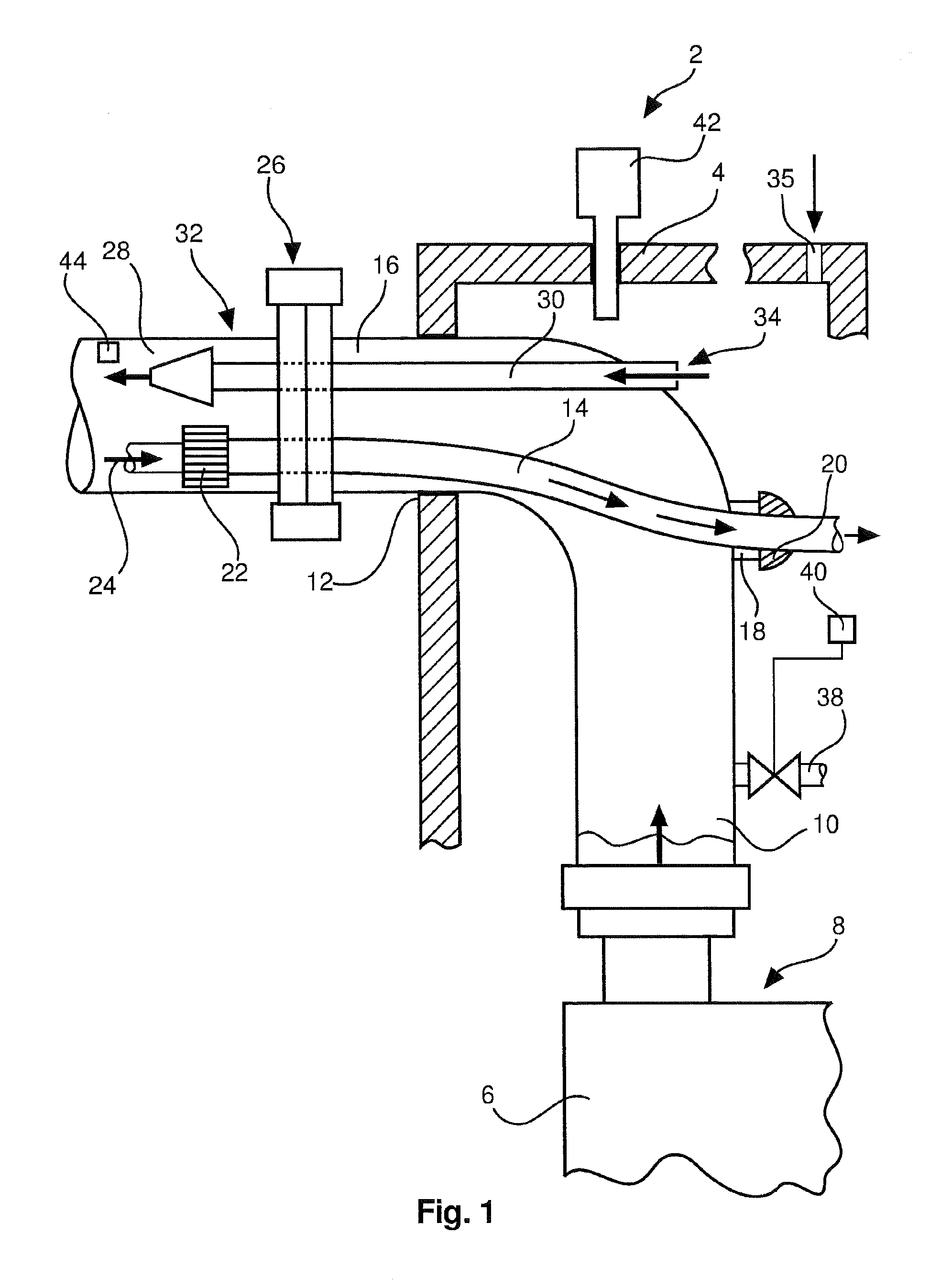
[0027]FIG. 1 shows a fuel cell system 2 comprising a housing 4 in which a fuel cell 6 is arranged. On a cathode side 8 an exhaust gas line 10 is connected that extends from the cathode side 8 through an opening 12 within the housing towards the outside.

[0028]A supply line 14 which extends from the outside into the interior of the housing 4 extends over a significant section within the exhaust gas line 10. The exhaust gas line 10 comprises a significantly larger diameter than the supply line 14. Between the supply line 14 and the exhaust gas line 10 a space 16 is thus formed that originates from exhaust gas from the cathode side 8 of the fuel cell 6.

[0029]The exhaust gas line 10 comprises an opening 18 through which the supply line 14 reaches the interior of the housing 4, for example by way of an elastic sleeve 20 to be sealed, which sleeve 20 clamps the supply line. At that point said supply line 14 can supply fuel cell fuel to the fuel cell 6 (not shown).

[0030]In the interior of t...


PUM

PropertyMeasurementUnit
temperatureaaaaaaaaaa
lengthaaaaaaaaaa

Abstract

A fuel cell system includes a fuel cell having a housing that encases the fuel cell, a supply line for a fuel cell fuel, and an exhaust gas line for fuel-cell exhaust gas. In this arrangement the supply line extends in the exhaust gas line, and the exhaust gas line encases the supply line while forming a space. Any leakage in the supply line thus results in the fuel being flushed out by means of the exhaust gases flowing in the exhaust gas line so that higher system reliability and a reduction in costs can be achieved.

Description

CROSS-REFERENCE TO RELATED APPLICATIONS[0001]The present application is a continuation of International Application No. PCT / EP2011 / 069953, filed Nov. 11, 2011, which claims priority from German Patent Application No. 10 2010 054 756.5 filed on Dec. 16, 2010, and which claims the benefit of the filing date of U.S. Provisional Patent Application No. 61 / 423,703 filed on Dec. 16, 2010, the disclosures of which are hereby incorporated herein by reference.TECHNICAL FIELD[0002]The invention relates to a fuel cell system, to the use of a fuel cell system, as well as to an aircraft comprising a fuel supply unit and such a fuel cell system.BACKGROUND OF THE INVENTION[0003]Fuel cell systems frequently comprise a housing that encloses one or several fuel cells and that comprises a connection for fuel cell fuel for supplying the fuel cell. By means of an exhaust gas line, exhaust gases are led to the outside by way of one or several separate exhaust gas connections. In addition, frequently, vent...

Claims


Application Information

Patent Timeline
Patent Type & Authority Applications(United States)
IPC IPC(8): H01M8/04
CPCH01M8/04201B64D41/00B64D2041/005H01M8/04089H01M8/04231H01M8/0662H01M8/2475Y02E60/50Y02T50/40Y02T90/40
Inventor KURRE, JENS-DIETRICHHOFFJANN, CLAUS
Owner AIRBUS OPERATIONS GMBH
Why Eureka
Try Eureka