Card member, card edge connector, and method for manufacturing card member

a card edge connector and card member technology, applied in the direction of coupling contact member, coupling device connection, printed circuit manufacturing, etc., can solve the problems of product quality, time-consuming and costly manufacturing, and inability to meet the needs of customers, so as to achieve smooth fitting section, no unevenness, and increase watertight properties.

Inactive Publication Date: 2013-10-31
JST MFG CO LTD
View PDF26 Cites 7 Cited by
  • Summary
  • Abstract
  • Description
  • Claims
  • Application Information

AI Technical Summary

Benefits of technology

[0028]According to the method for manufacturing a card member of the above aspect, because the joining portion of the first mold and the second mold is disposed so as not to be overlapped with the fitting section when the resin molded section of the card member is formed, the burr (parting line) formed in the portion where the first mold and the second mold are joined during mold-forming is not formed in the fitting section of the card member. Therefore, according to the method for manufacturing card member of this aspect, there is no unevenness in the fitting section even when the card member is fitted with the opposing connector, and the watertight property can therefore be increased. According to the method for manufacturing card member of this aspect, because the burr is not formed in the fitting section, there is no need to remove burrs as in conventional practice, and a smooth fitting section can be obtained.
[0029]According to the method for manufacturing a card member of the above aspect, because the joining portion of the first mold and the second mold is disposed in a direction perpendicular to the direction in which the card edge section protrudes when the resin molded section of the card member is formed, the burr is formed in a position excluding the fitting section of the card member, and because the burr is formed in a direction perpendicular to the direction in which the card edge section protrudes, formation of the burr on the fitting section can be better avoided.
[0030]According to the method for manufacturing a card member of the above aspect, by disposing the substrate oriented vertically inside the first mold and the second mold, the joining portion of the first mold and the second mold can be disposed perpendicular to the flat surface of the substrate so as to not correspond with the fitting section of the resin molded section of the card member even if a vertical molding machine is used, and a card member in which a burr is not formed on the fitting section can be manufactured more efficiently. According to the method for manufacturing a card member of the above aspect, because a cut is made in the molds so that the substrate can be disposed vertically, more card members can be obtained in a single molding than in cases in which the substrat

Problems solved by technology

When a small gap is formed, liquid adhering to the connector could infiltrate the connector through capillarity, and there is a risk of problems occurring with the electronic equipment, causing malfunctions and breakdowns.
The burr could also be removed by polishing after the mold-formation, but manufacturing becomes more time-consuming and costly because a polishing step is needed, and there is a risk of problems with product quality in that the size and shape is different than what was designed when the equipment is grinded down by polishing.
If a groove for accommodating the sealing member is formed, as is the case with the electronic circuit device disclosed in Japanese Patent Publication No. 4478007, because the

Method used


Image

  • Card member, card edge connector, and method for manufacturing card member
  • Card member, card edge connector, and method for manufacturing card member
  • Card member, card edge connector, and method for manufacturing card member

Examples


embodiment

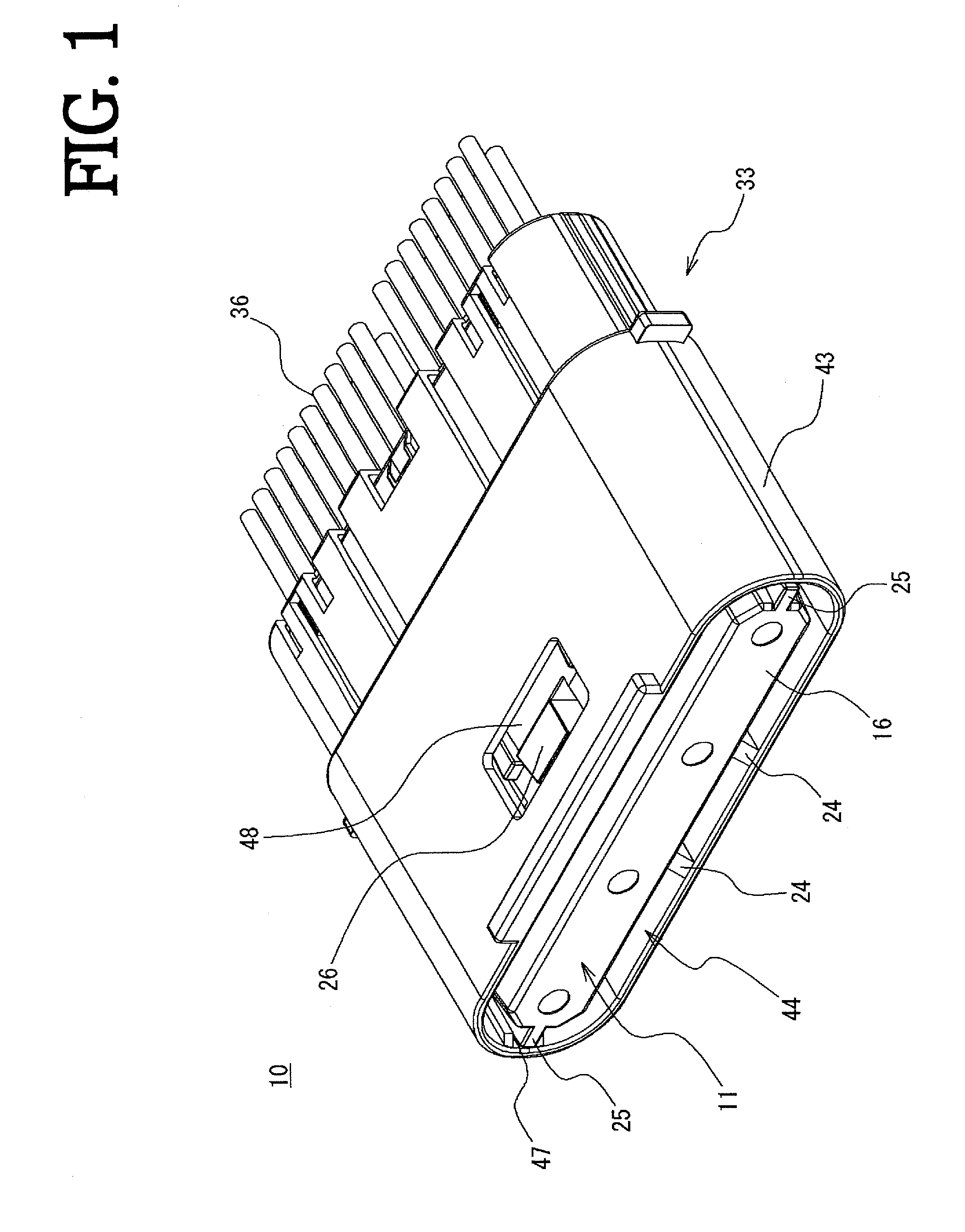
[0059]A card edge connector 10 and its manufacturing method in one exemplary embodiment are described with reference to FIGS. 1 to 12. The card edge connector 10 is configured from a card member 11 and an opposing connector 33 to which the card member 11 is connected, as shown in FIG. 1.

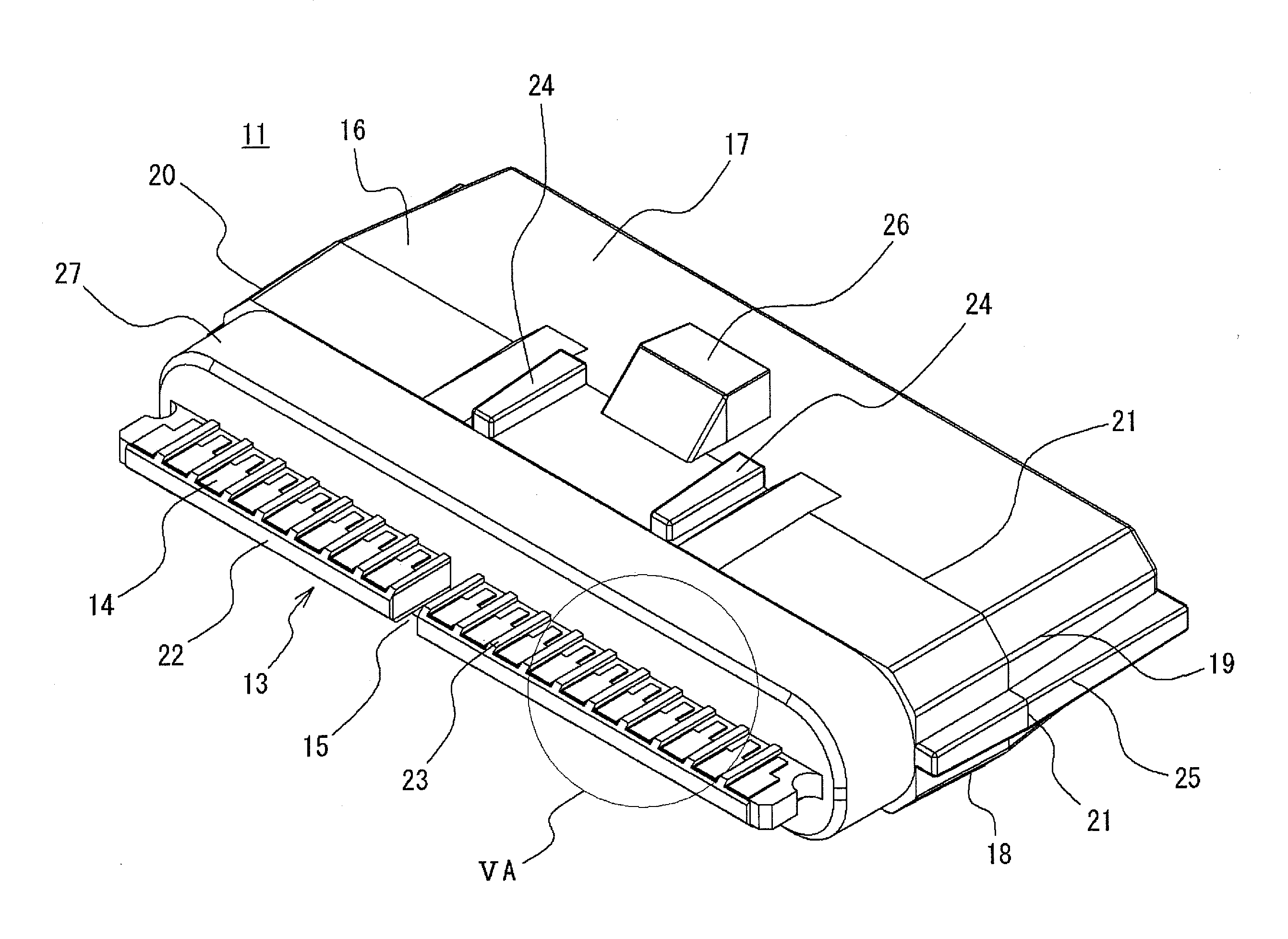
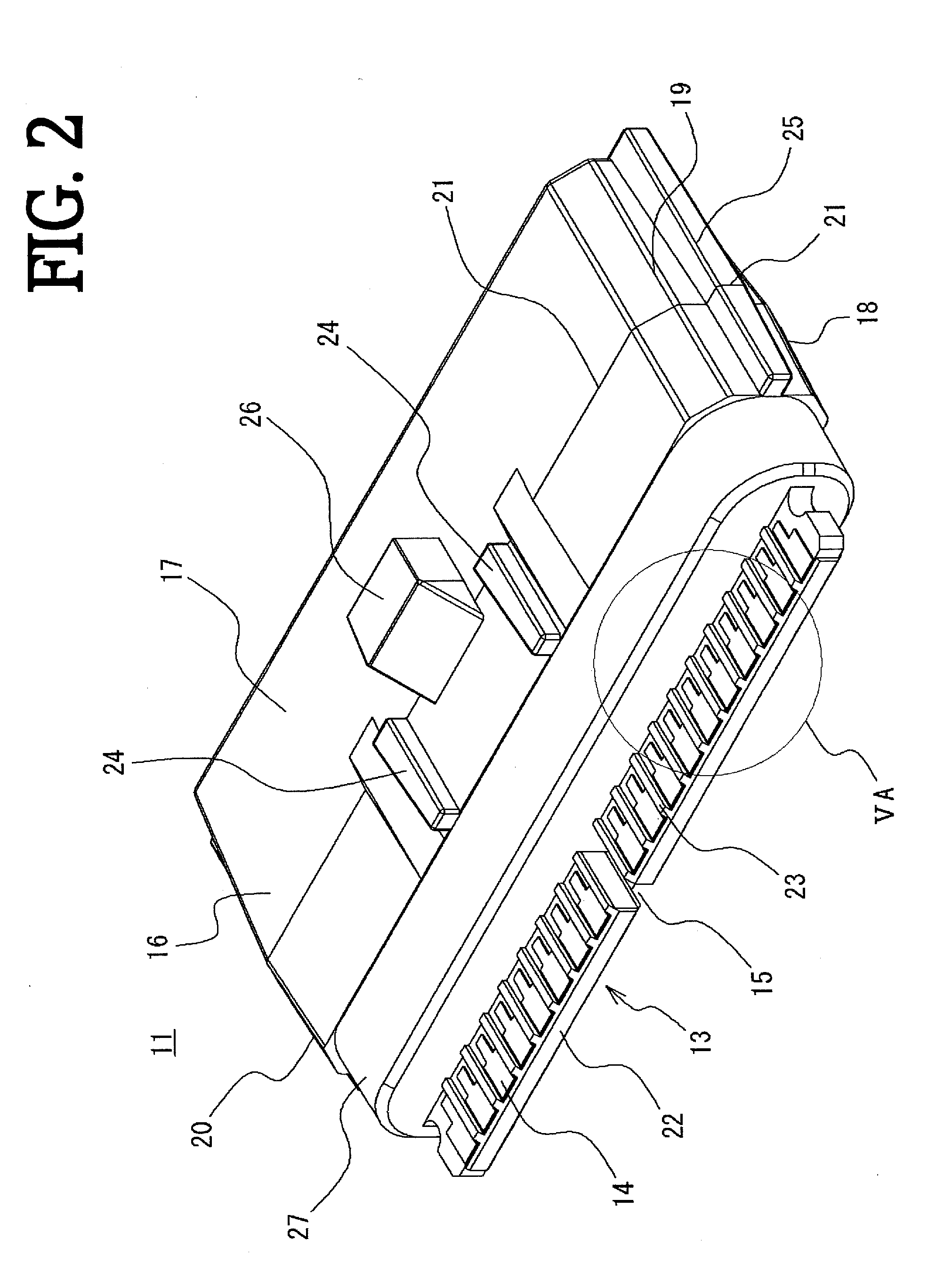
[0060]First, the card member 11 of the embodiment shall be described with reference to FIGS. 1 through 5. The card member 11 is configured from: a substrate 12 having a plurality of card edge terminals 14 formed thereon, the card edge terminals being in contact with a contact 34 (see FIG. 11) having circuit wiring or the like printed thereon and provided at one end to the opposing connector 33; and a resin molded section 16 molded integrally from a synthetic resin material so that the card edge section of the substrate 12 protrudes, as shown in FIGS. 2 and 3.

[0061]The substrate 12 has a printed circuit and various electronic components or integrated circuits or the like disposed on the front surface ...


PUM

PropertyMeasurementUnit
Moldableaaaaaaaaaa

Abstract

A method for manufacturing a card member includes: preparing a substrate having a card edge section with card edge terminals to be connected to an opposing connector; preparing a fist mold and a second mold that have molding spaces for molding a resin molded section having a fitting section to be fitted with the opposing connector formed around the substrate; placing the substrate inside the molding spaces between the first mold and the second mold in such a way that the joining portion of the first mold and the second mold are disposed so as not to be overlapped with the portion where the fitting section is to be formed; injecting a synthetic resin material into the molding space to integrally form the resin molded section around the substrate. The method can provide a card member having an excellent watertightness.

Description

CROSS REFERENCE TO RELATED APPLICATIONS[0001]This application claims priority to Japanese Patent Application No. 2012-103112 filed on Apr. 27, 2013, the entire contents of which are incorporated by reference herein.TECHNICAL FIELD[0002]The present invention relates to a card member, a card edge connector, and a method for manufacturing a card member, wherein a substrate having card edge terminals connected to an opposing connector is molded integrally from a synthetic resin material. Specifically, the present invention relates to a card member, a card edge connector, and a method for manufacturing a card member wherein a burr (parting line) formed on a joining portion of molds during mold-forming process is not formed on a watertight portion tightly connected to an opposing connector.BACKGROUND ART[0003]An electronic device for an apparatus used outdoors, a typical example being a vehicle such as an automobile or an automatic two-wheeler, uses a card member, an electronic circuit ap...

Claims


Application Information

Patent Timeline
IPC IPC(8): H01R13/52
CPCH01R13/52H01R12/721H01R13/5219H01R43/24H05K1/117H05K3/0097H05K3/284H05K2203/1316H05K2203/1327H01R4/188H01R4/184
Inventor NAGAMINE, AKIRA
Owner JST MFG CO LTD
Why Eureka
Try Eureka