Reconfigurable stent-graft delivery system and method of use

a stent and graft technology, applied in the field of stent graft delivery systems, can solve the problems of aaa having diseased or damaged proximal necks, increasing the number of interventional devices needed to complete the procedure, and complicated procedures

Active Publication Date: 2013-10-31
MEDTRONIC VASCULAR INC
View PDF5 Cites 28 Cited by
  • Summary
  • Abstract
  • Description
  • Claims
  • Application Information

AI Technical Summary

Benefits of technology

[0008]Another embodiment hereof is directed to a method of using the delivery system. The delivery system is first used in the multi-lumen delivery catheter configuration for delivering and staging the release of a main vessel stent-graft that is configured for placement in the abdominal aorta for treatment of short-neck infrarenal, juxtarenal, and / or suprarenal aneurysms. The delivery system is then used in the delivery sheath configuration for introducing medical devices that deliver branch vessel stent-grafts, which are configured to extend from the main vessel stent-graft into respective renal arteries.

Problems solved by technology

Although the endovascular approach is much less invasive, usually requiring less recovery time and involving less risk of complication as compared to open surgery, there can be concerns with anchoring and alignment of prostheses in relatively complex AAA applications such as ones involving branch vessels.
The procedure becomes more complicated and the number of interventional devices needed to complete the procedure increases when more than one branch vessel is treated.
For example, an AAA may occur having a proximal neck that is diseased or damaged to the extent that it cannot support an effective seal and connection with a prosthesis, such as is the case with short neck infrarenal, juxtarenal and surprarenal aneurysms.
A consequence of current treatments for AAA with the delivery of multiple stent-grafts that mate together to form a partial or complete implant are lengthy procedure times and the potential for patient harm that may be associated with delivery of the multiple interventional devices that are currently necessary to perform the delivery, positioning and assembly of the stent-graft segments.

Method used


Image

  • Reconfigurable stent-graft delivery system and method of use
  • Reconfigurable stent-graft delivery system and method of use
  • Reconfigurable stent-graft delivery system and method of use

Examples


Embodiment Construction

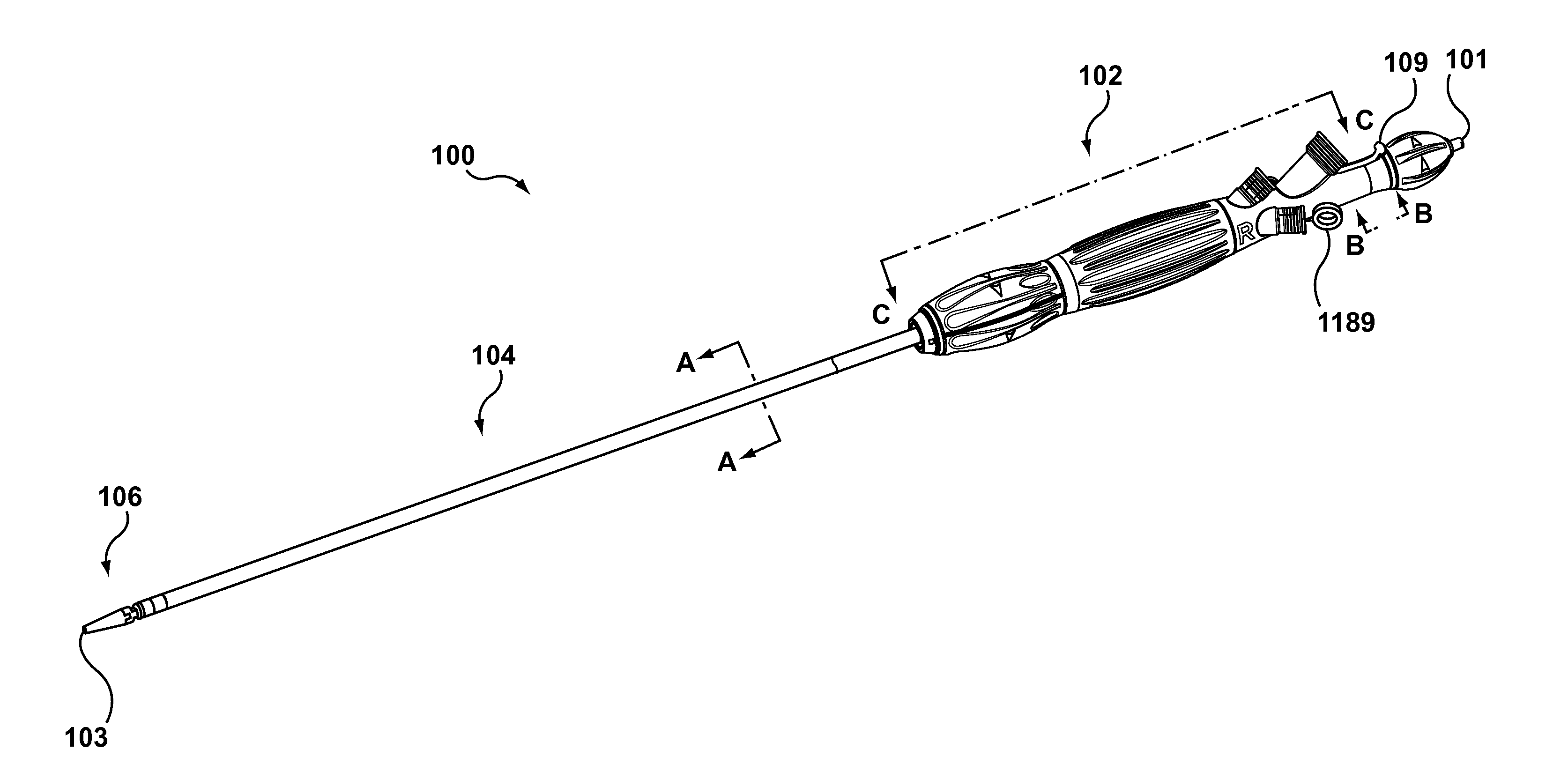
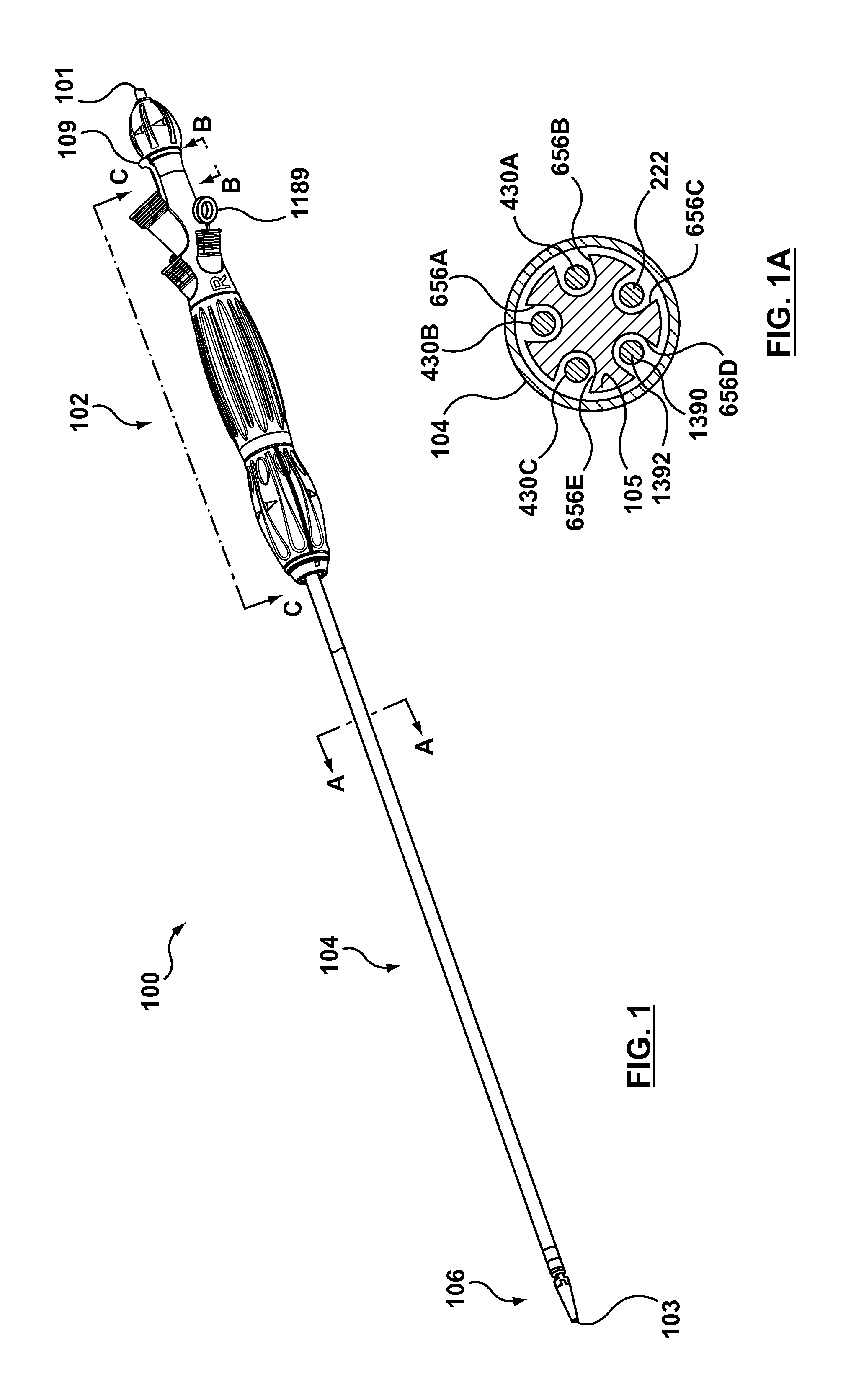
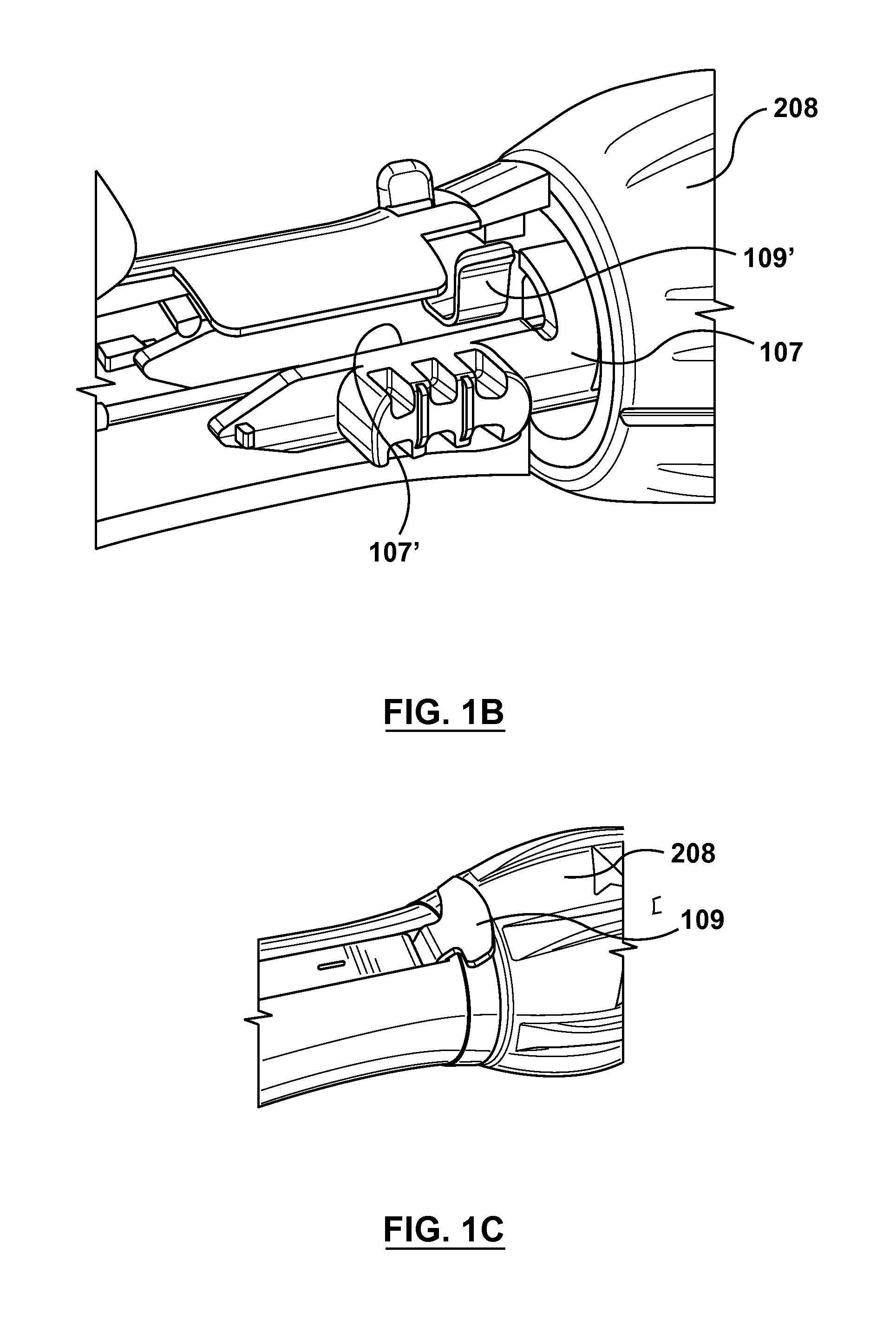
[0031]Specific embodiments of the present invention are now described with reference to the figures, wherein like reference numbers indicate identical or functionally similar elements. Regarding “proximal” and “distal” positions referenced herein, a proximal end of a prosthesis, e.g., stent-graft, is the end closest to the heart by way of blood flow path whereas a distal end of the prosthesis is the end furthest away from the heart during deployment. In contrast, a distal end of the stent-graft delivery system or other associated delivery apparatus is usually identified as the end that is farthest from the operator, while a proximal end of the delivery system and devices is the end nearest the operator or handle of the catheter. In addition, the term “self-expanding” is used in the following description with reference to one or more stent structures of the prostheses hereof and is intended to convey that the structures are shaped or formed from a material that can be provided with a...


PUM


Abstract

A reconfigurable delivery system is disclosed having a multi-lumen delivery catheter configuration that permits the delivery and staged release of a self-expanding main vessel stent-graft and a delivery sheath configuration that permits the introduction of various medical devices for the delivery and implantation of various branch vessel stent-grafts that are to be mated with the main vessel stent-graft. A method is disclosed wherein the delivery system is first used in the multi-lumen delivery catheter configuration to deliver and release a main vessel stent-graft that is configured for placement in the abdominal aorta for treatment of short-neck infrarenal, juxtarenal, and/or suprarenal aneurysms and then used in the delivery sheath configuration to facilitate the delivery of branch vessel stent-grafts that are configured to extend from the main vessel stent-graft into a respective renal artery.

Description

FIELD OF THE INVENTION[0001]The invention relates to stent-graft delivery systems and more particularly to a stent-graft delivery system for delivering and implanting mating stent-graft segments.BACKGROUND OF THE INVENTION[0002]Tubular prostheses, such as stents, grafts, and stent-grafts are known for treating abnormalities in various passageways of the human body. In vascular applications, these devices often are used to replace or bypass occluded, diseased or damaged blood vessels such as stenotic or aneurysmal vessels. For example, it is well known to use stent-grafts of a biocompatible graft material supported by a framework, for e.g., one or more stent or stent-like structures, to treat or isolate aneurysms. The framework provides mechanical support and the graft material or liner provides a blood barrier. When implanting a stent-graft, the stent-graft typically is placed so that one end of the stent-graft is situated proximal to or upstream of the diseased portion of the vesse...

Claims


Application Information

Patent Timeline
Patent Type & Authority Applications(United States)
IPC IPC(8): A61F2/84
CPCA61F2002/061A61F2002/075A61F2002/9511A61F2250/006A61M25/00A61F2002/9505A61F2/954A61F2/9517
Inventor MAGGARD, JASONARGENTINE, JEFFERYHAGGARD, MATHEWPEARSON, MEGHANSIMMONS, EMILIE
Owner MEDTRONIC VASCULAR INC
Why Eureka
Try Eureka