
Voiced Interval Command Interpretation
a voice and interval technology, applied in the field of voice activation technology, can solve the problems of inability to achieve economic development, inability to support single-purpose devices, and inability to achieve full speech recognition, etc., and achieve the effects of high sensitivity, fast recording, and increased gain
- Summary
- Abstract
- Description
- Claims
- Application Information
AI Technical Summary
Benefits of technology
Problems solved by technology
Method used
Image

Examples
Embodiment Construction
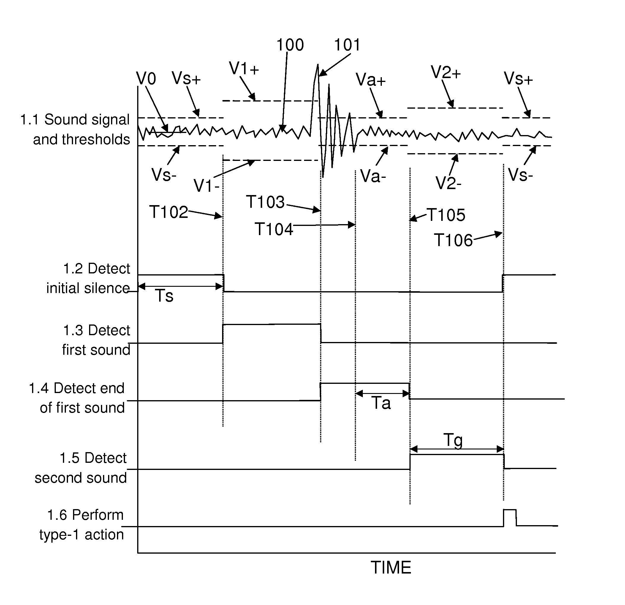
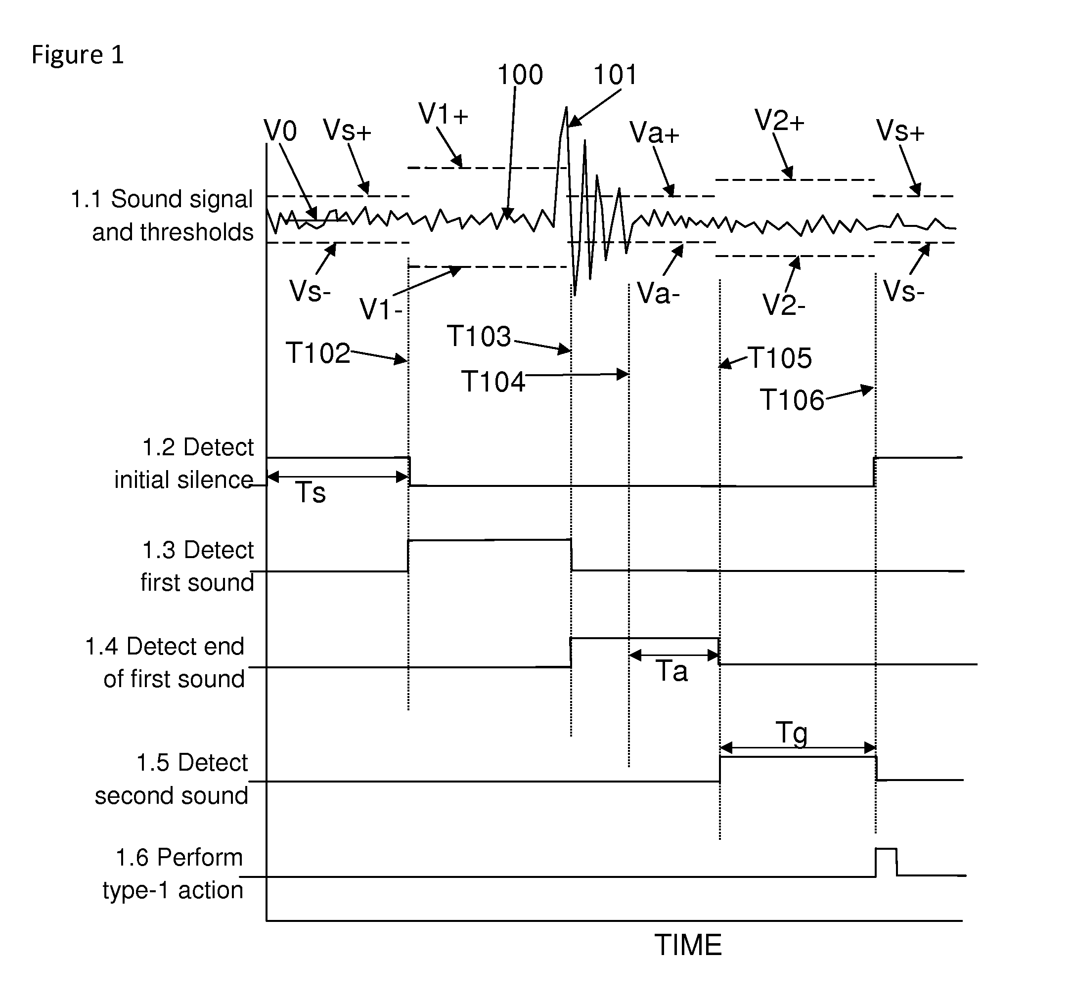
[0050]FIG. 1 shows a series of graphs or traces, similar to oscilloscope traces, showing how the inventive method is used to interpret a type-1 command. The first trace in FIG. 1, labeled “1.1 Sound signal and thresholds”, shows the amplified and filtered analog sound signal 100, with voltage on the vertical axis and time on the horizontal axis. The sound signal 100 is bipolar, not rectified, and thus exhibits both positive and negative excursions relative to the mean signal during silence. The voiced interval 101 of a type-1 command can be seen on the sound signal 100, as well as continuous low-amplitude variations due to electronic noise. Various threshold values are also shown as dashed horizontal lines. A solid horizontal line labeled V0 indicates the mean silent signal. Certain times are also indicated by vertical dotted lines.
[0051]The second trace in FIG. 1, labeled “1.2 Detect initial silence”, shows a time period of length Ts which is demarked to determine that all prior so...
PUM
 Abstract
Description
Claims
Application Information