Purge method and purge unit for gas turbine combustor

a gas turbine and purge unit technology, applied in the direction of turbine/propulsion fuel valves, mechanical devices, machines/engines, etc., can solve the problems of generating combustion oscillation, affecting the efficiency of gas turbine combustor purging, so as to achieve effective prevention of deviation

Active Publication Date: 2013-11-07
MITSUBISHI POWER LTD
View PDF4 Cites 16 Cited by
  • Summary
  • Abstract
  • Description
  • Claims
  • Application Information

AI Technical Summary

Benefits of technology

[0051]According to the present invention, it is possible to effectively prevent deviation of the exhaust gas environmental regulation value from the regulation range by surely removing the residual oil from the oil fuel line by combining the first purge step of purging immediately after the fuel is switched to the gas fuel and the second purge step of purging immediately before the fuel is switched to the oil fuel.

Problems solved by technology

This causes blockage of the nozzle.
Even if the nozzle is not completely blocked, a fuel injection amount from the nozzle deviates from a desired value in some cases, which could result in generation of combustion oscillation, deviation of exhaust gas environmental regulation value (NOx amount, CO amount) from a regulation range, etc.
This requires the gas turbine to be shut down temporarily, missing a power generation opportunity.

Method used


Image

  • Purge method and purge unit for gas turbine combustor
  • Purge method and purge unit for gas turbine combustor
  • Purge method and purge unit for gas turbine combustor

Examples


working example

[0110]The following experiments were made to study the effect of the purging method for the combustor according to the above embodiment on the exhaust gas environmental regulation value. More specifically, for the gas turbine equipped with the dual-fuel type combustor 1, three types of purge processes, Working Example, Comparison Example 1 and Comparison Example 2 were performed, and content in the exhaust gas was analyzed and exhaust gas CO concentration [ppm] at standard O2 concentration 15% was obtained. The details of each purging method are described below. Since there was variation in the results of CO concentration analysis, data regarding the results of the CO concentration analysis was collected by repeating multiple times the purging process under the conditions of Working Example, Comparison Example 1 and Comparison Example 2 and then analyzing the exhaust gas CO concentration.

[0111]The conditions of the purging process in Working Example, Comparison Example 1 and Compari...


PUM


Abstract

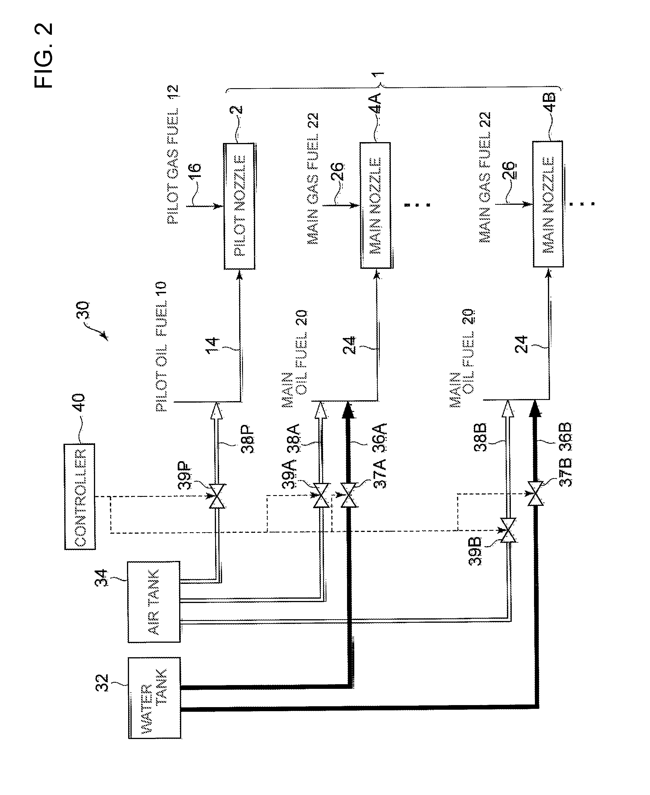
A purging method and a purge unit for a gas turbine combustor capable of effectively preventing deviation of an exhaust gas environmental regulation value from a regulation range in the case of using a dual-fuel type gas turbine combustor. The gas turbine combustor is provided with nozzles. Which communicate with an oil fuel line where oil fuel flows and a gas fuel line where gas fuel flows and are capable of switching injection fuel between the oil fuel and the gas fuel. A purging method for the gas turbine includes a first purge step of purging the oil fuel line by at least water immediately after the injection fuel is switched to the gas fuel from the oil fuel and a second purge step of purging the oil fuel line by at least water immediately before the injection fuel is switched to the oil fuel from the gas fuel.

Description

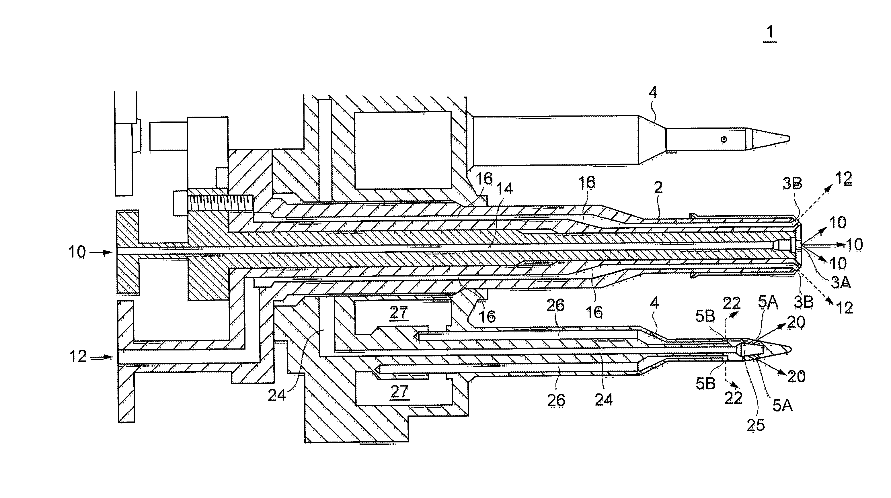
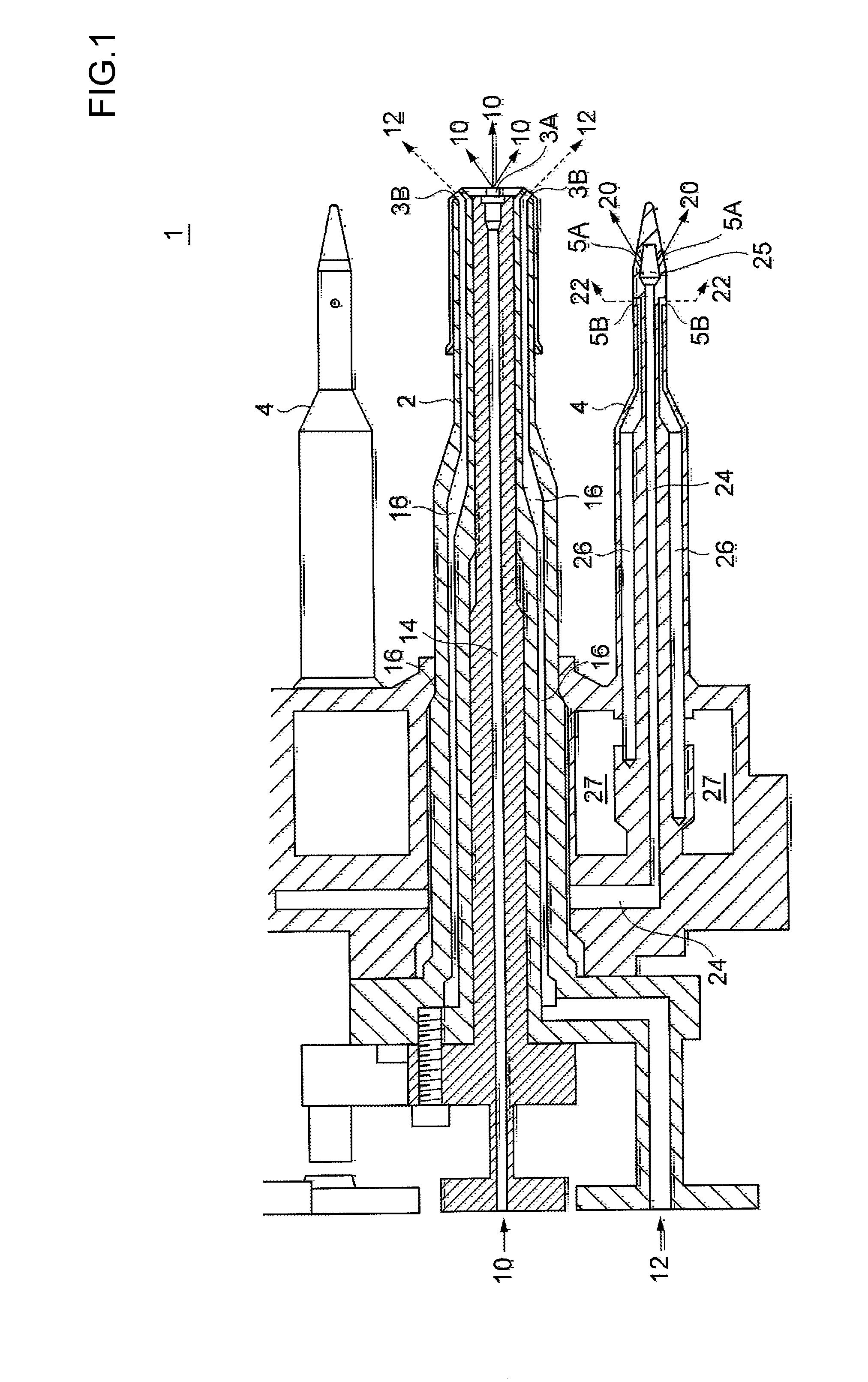
TECHNICAL FIELD [0001]The present invention relates to a purging method and a purge unit for a dual-fuel type gas turbine combustor provided with a nozzle capable of switching injection fuel between oil fuel and gas fuel.BACKGROUND ART[0002]To be compatible with a various types of fuel including liquid oil fuel such as fuel oil, diesel fuel and liquefied petroleum gas (LPG), and gas fuel such as natural gas and coal gas, a dual-fuel type gas turbine combustor capable of switching the fuel to be used between the oil fuel and the gas fuel has been known.[0003]In a dual-fuel type gas turbine combustor, once the fuel to be used is switched to gas fuel from oil fuel, it is inevitable that the oil fuel remains in a passage (an oil fuel line) for introducing the oil fuel to a nozzle. This residual oil cokes from being exposed to a high temperature environment resulting from combustion of the gas fuel. This causes blockage of the nozzle. Even if the nozzle is not completely blocked, a fuel ...

Claims


Application Information

Patent Timeline
Patent Type & Authority Applications(United States)
IPC IPC(8): F02C7/00
CPCF02C7/00F02C7/232F02C9/40
Inventor OCHIAI, YOSHIAKI
Owner MITSUBISHI POWER LTD
Why Eureka
Try Eureka