
Electronic device and heat dissipation module thereof

a technology of electronic devices and heat dissipation modules, which is applied in the direction of cooling/ventilation/heating modifications, instruments, lighting and heating apparatus, etc., can solve the problems of module not immediately bringing out heat, user may not install programs or save data in the thin client, and the thin client without saving functions is uneasily affected by viruses

Active Publication Date: 2013-11-07
INVENTEC PUDONG TECH CORPOARTION +1
View PDF11 Cites 55 Cited by
  • Summary
  • Abstract
  • Description
  • Claims
  • Application Information

AI Technical Summary

Benefits of technology

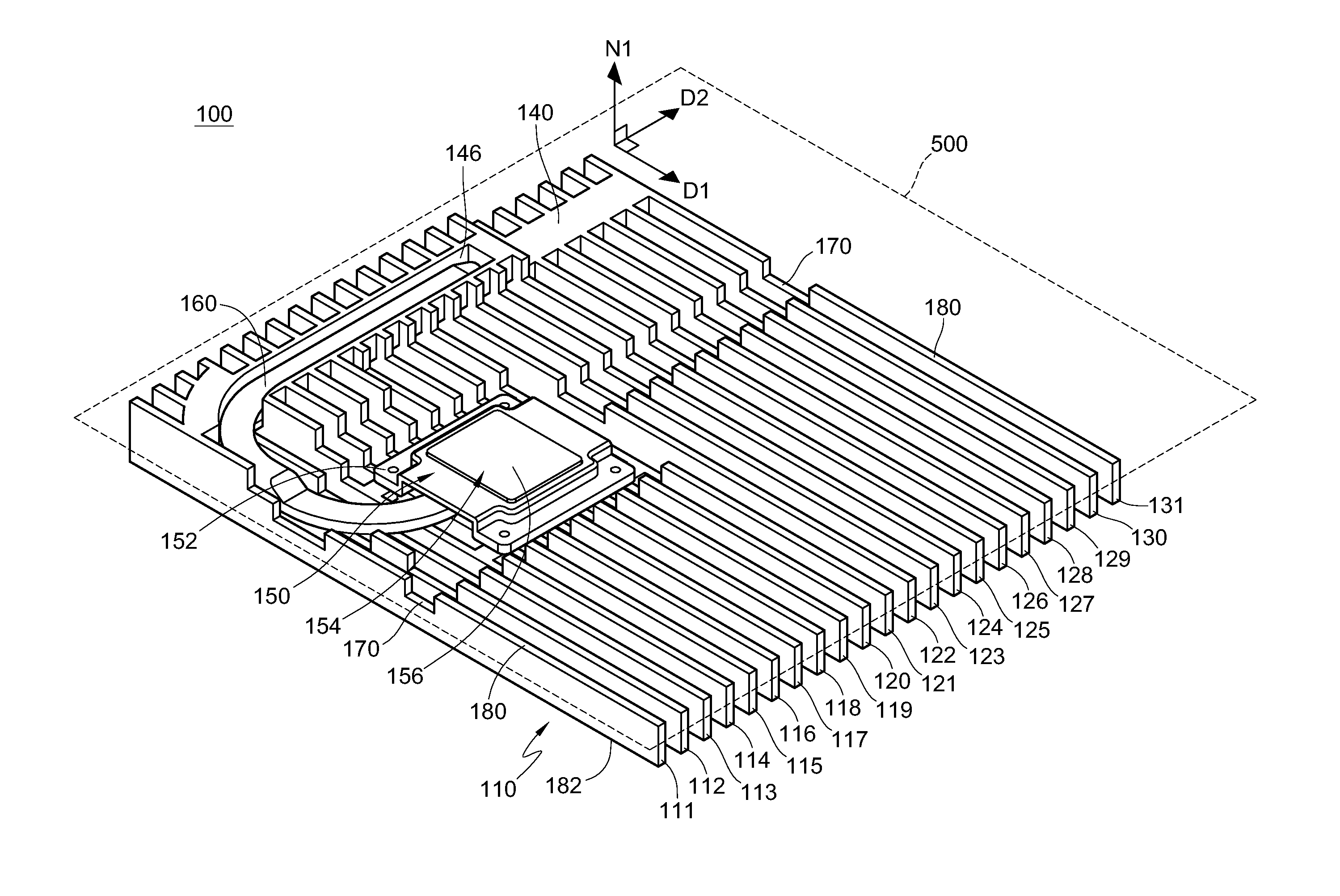
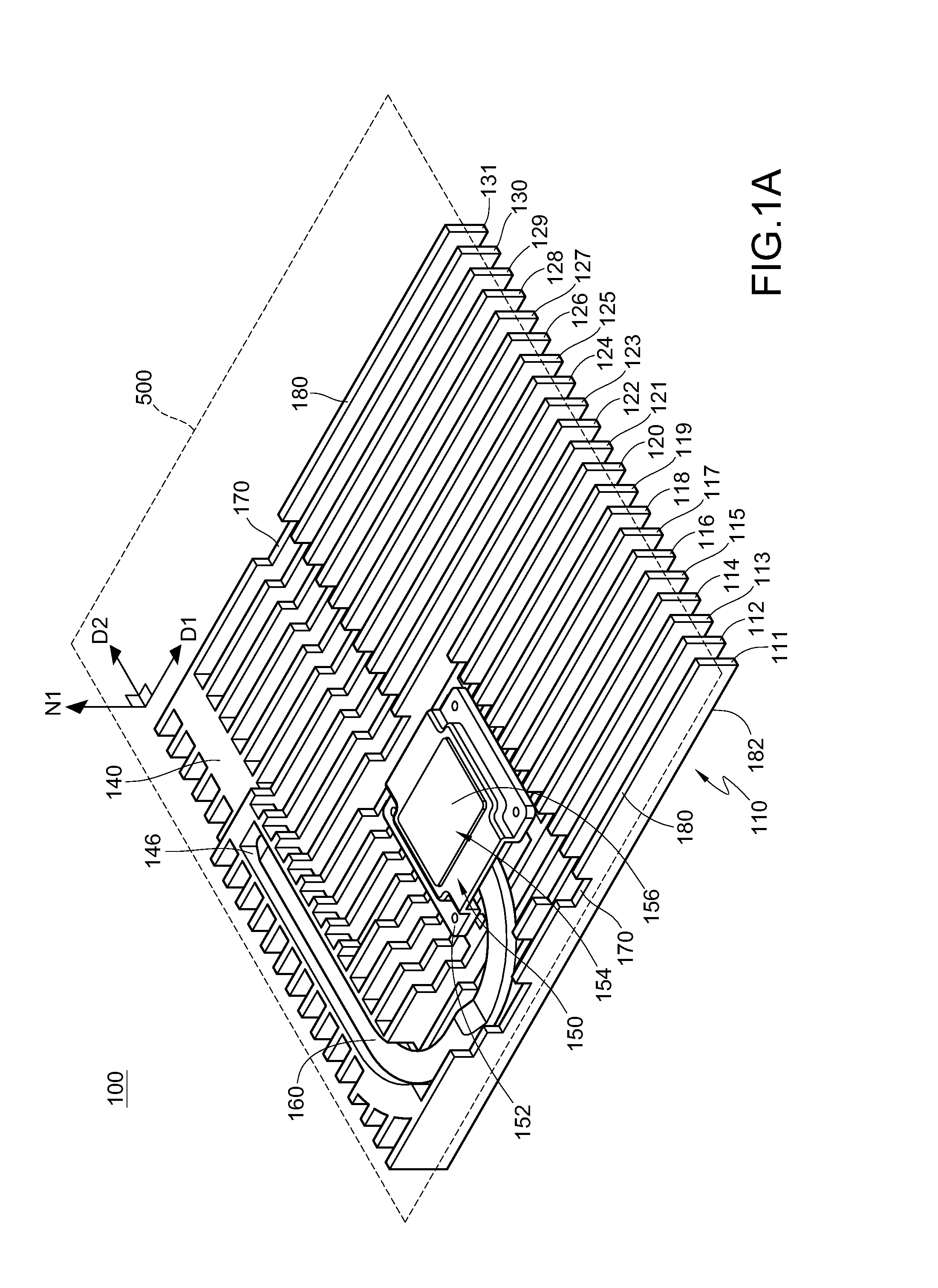
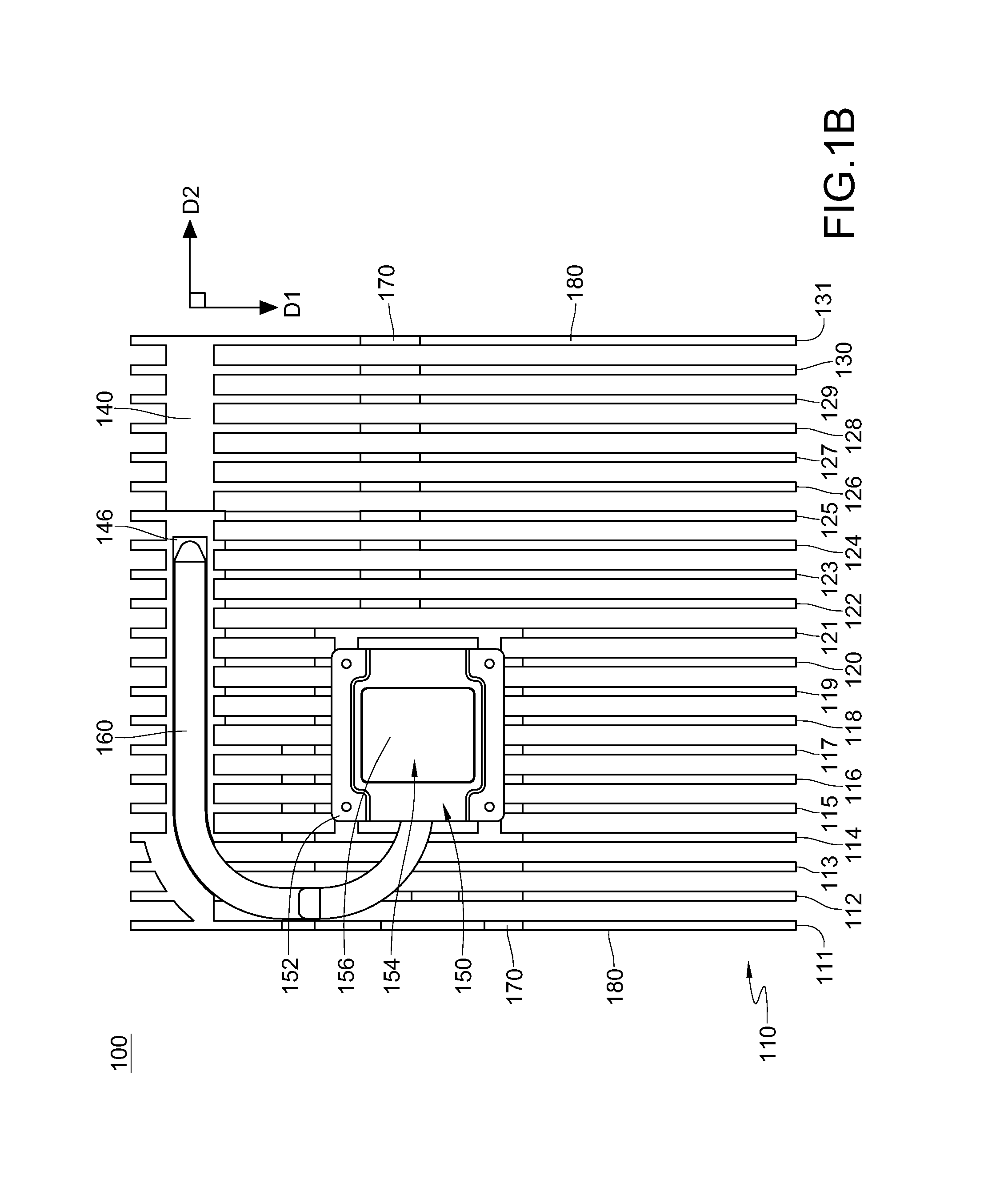
The patent describes heat dissipation modules that are used to prevent overheating of electronic devices. These modules have a fin assembly, connecting part, and heat pipe that are integrated into one piece using die casting. The fin assembly is placed on the device's mainframe and includes multiple fin elements that extend in one direction. The connecting part is connected to the fin elements and also extends in another direction. The fin assembly and connecting part form a first angle greater than 0 degree. The heat dissipation module is in thermal contact with the electronic element and helps to distribute heat away from the device, improving its performance.

Problems solved by technology

Therefore, the user may not install programs or save data in the thin client, otherwise, the data are saved in the server.
That is, the thin client without saving function is uneasily affected by virus.
But the thin client without the active heat dissipation module may not bring the heat out immediately due to the increasing operating frequency of the electronic element.
When the heat which is generated by the electronic element may not be removed by the heat dissipation plate, the excess heat will affect the stability of the operated thin client.

Method used


Image

  • Electronic device and heat dissipation module thereof
  • Electronic device and heat dissipation module thereof
  • Electronic device and heat dissipation module thereof

Examples


Embodiment Construction

[0024]The detailed features and advantages of the disclosure are described below in great detail through the following embodiments, the content of the detailed description is sufficient for those skilled in the art to understand the technical content of the present disclosure and to implement the disclosure there accordingly. Based upon the content of the specification, the claims, and the drawings, those skilled in the art can easily understand the relevant objectives and advantages of the disclosure.

[0025]It will be understood that, relative terms, such as “lower” or “bottom”, “on” or “top”, “left” or “right” may be used herein to describe one element's relationship to another element as illustrated in the Figures. It will be understood that relative terms are intended to encompass different orientations of the device in addition to the orientation depicted in the Figures. For example, if the device in one of the figures is turned over, elements described as being on the “lower” s...


PUM


Abstract

The disclosure provides an electronic device and a heat dissipation module having an imaginary structural plane. The heat dissipation module includes a fin assembly, a connecting part and a heat pipe. The fin assembly is disposed on the structural plane and includes a plurality of fin elements extending along a first direction. The connecting part is connected to the fin elements. The fin elements are connected to each other via the connecting part. At least one portion of the connecting part is connected to at least one portion of the heat pipe, and the connecting part and the heat pipe both extend along a second direction. The fin assembly and the connecting part are integrated and formed into one piece by die casting. The first direction and the second direction form a first included angle greater than 0 degree.

Description

CROSS-REFERENCE TO RELATED APPLICATIONS[0001]This non-provisional application claims priority under 35 U.S.C. §119(a) on Patent Application No(s). 101116032 filed in Taiwan, R.O.C. on May 4, 2012, the entire contents of which are hereby incorporated by reference.BACKGROUND[0002]1. Technical Field[0003]The present disclosure relates to an electronic device and a heat dissipation module thereof, and more particularly, to an electronic device and a heat dissipation module thereof having multiple fin elements.[0004]2. Related Art[0005]Compared to a general computer, a thin client is a low-level computing apparatus without built-in compact disc driver, hardware device, soft disc driver and other unnecessary soft / hardware device or function. The thin client is connected to a server which stores application programs and information data of the thin client. When the thin client is operated by a user, the thin client transmits a command of the user to the server to execute operation of the c...

Claims


Application Information

Patent Timeline
Patent Type & Authority Applications(United States)
IPC IPC(8): H05K7/20F28D15/02
CPCH05K7/20336F28D15/02F28D15/0275G06F1/203H05K7/20445
Inventor WANG, FENG-KUCHENG, YI-LUNYANG, CHIH-KAIWU, WEI-HSINCHEN, HUA-FENGLIN, MING-HUNG
Owner INVENTEC PUDONG TECH CORPOARTION
Learn More