
Llc resonant power converter with current-circulating circuit for enabling light-load regulation

a current-circulating circuit and power converter technology, applied in the direction of electric variable regulation, process and machine control, instruments, etc., can solve the problem of excessive energy accumulation in parasitic capacitances, the inability of llc resonant power converters to regulate output voltage under light load, and the inability to perform light-load regulation. , to achieve the effect of enabling light-load regulation

Inactive Publication Date: 2013-11-07
SKYNET ELECTRONICS
View PDF6 Cites 15 Cited by
  • Summary
  • Abstract
  • Description
  • Claims
  • Application Information

AI Technical Summary

Benefits of technology

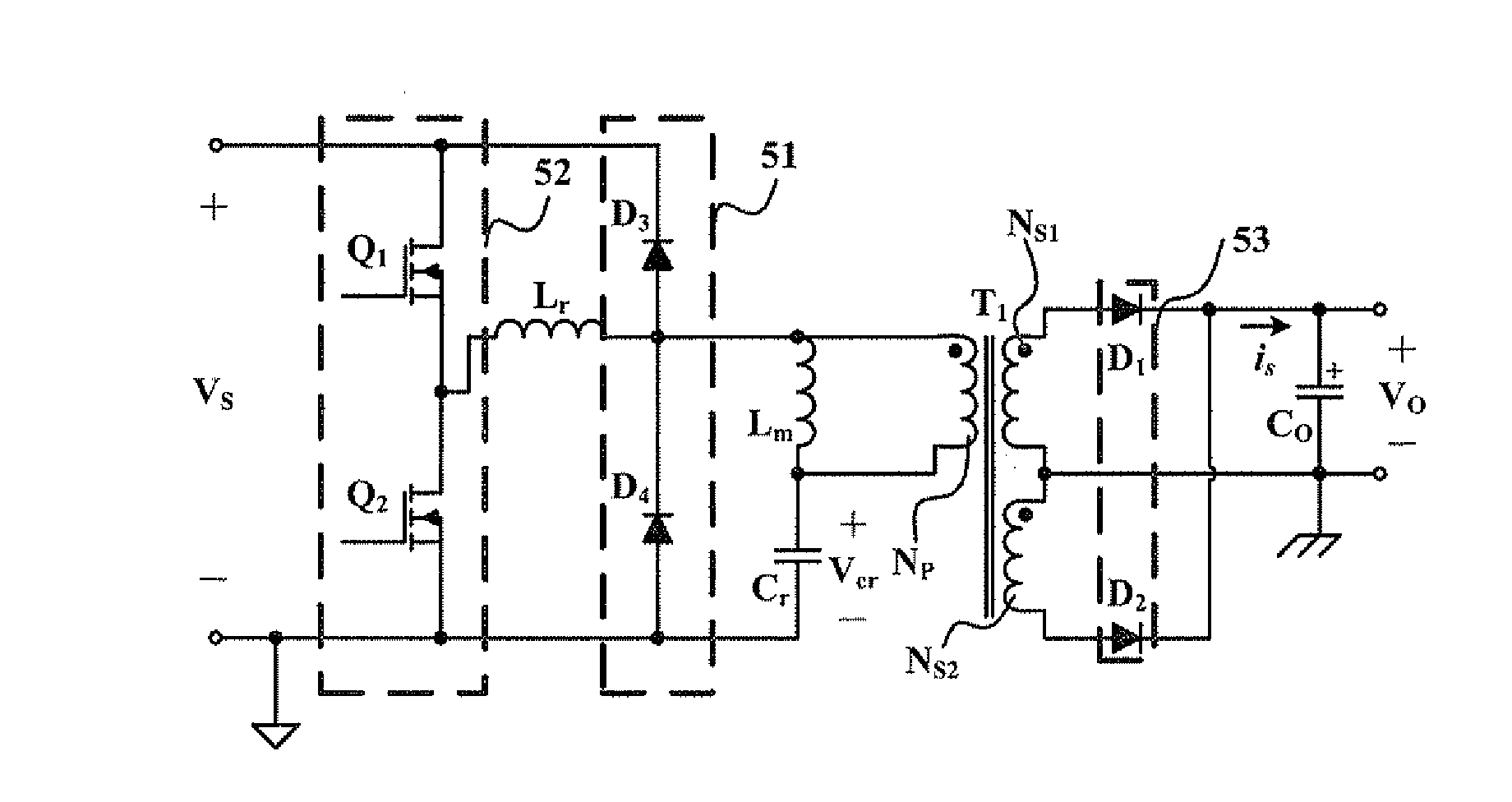
The present invention is a new type of LLC resonant power converter that prevents excessive energy from accumulating in the converter's components, which can cause damage. This is achieved by using a current-circulating circuit, which guides the current through the resonant inductor into circulation in the switching moment of the power switches. This prevents the parasitic capacitance of the primary winding from resonating with the resonant inductor and from being overcharged. As a result, the output voltage of the converter is effectively maintained in a certain range, even when the load is very small.

Problems solved by technology

At the same time, however, the incapability of LLC resonant power converters to regulate output voltage under light load, i.e., to perform light-load regulation, has become an issue.
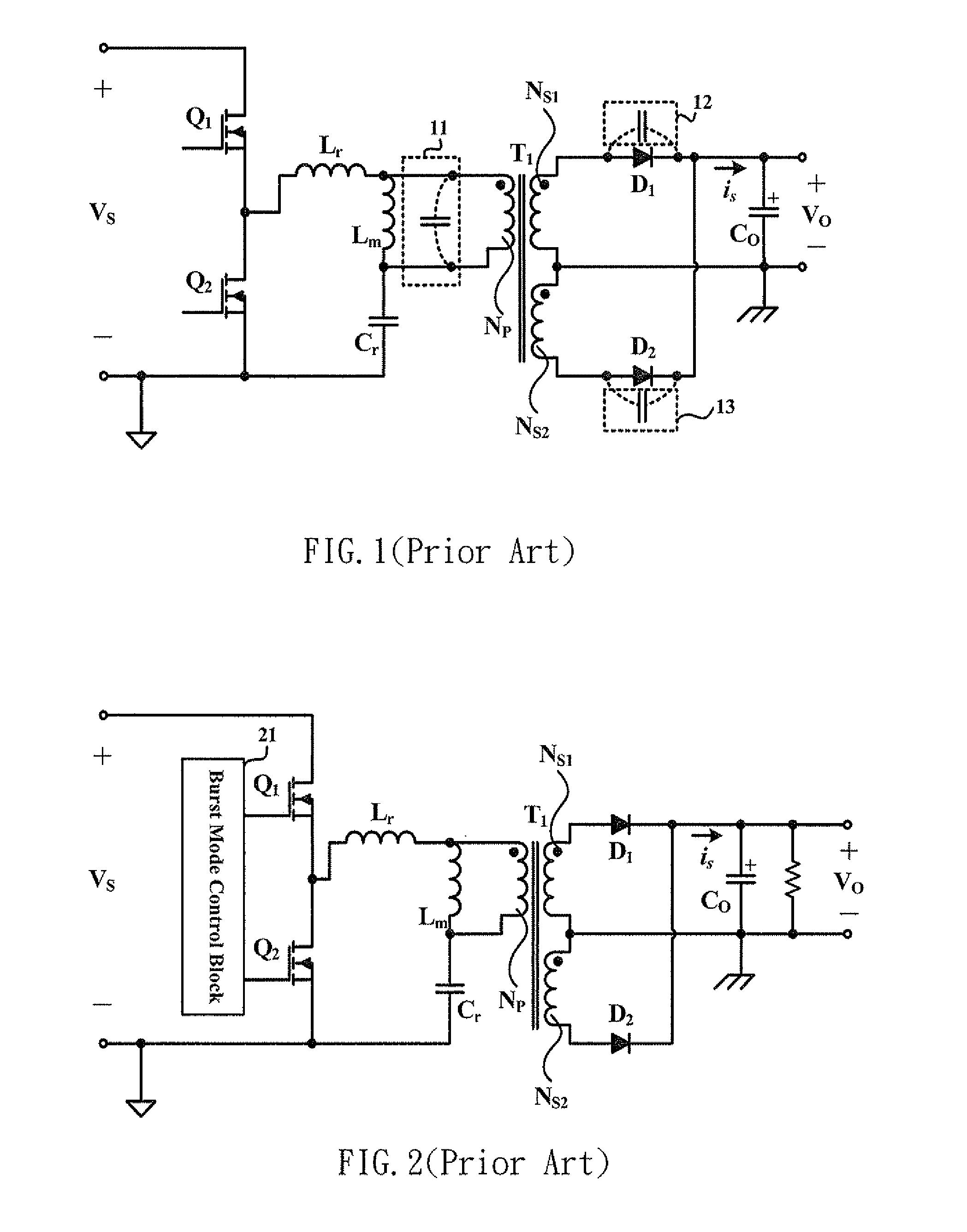
FIG. 1 shows a conventional LLC resonant power converter, the main reason why this conventional LLC resonant power converter is incapable of light-load regulation is that, in the moment when the power switches are switched, the parasitic capacitance of the primary winding NP and the parasitic capacitances 12 and 13 of the rectifiers in the full-wave rectification circuit on the secondary side are bound to resonate with the resonant inductor LT, such that excessive energy accumulates in the parasitic capacitances.
Hence, although this approach is effective in regulating the output voltage Vo and keeping it in the designed range, the annoying noise causes a certain degree of noise pollution around the LLC resonant power converter.
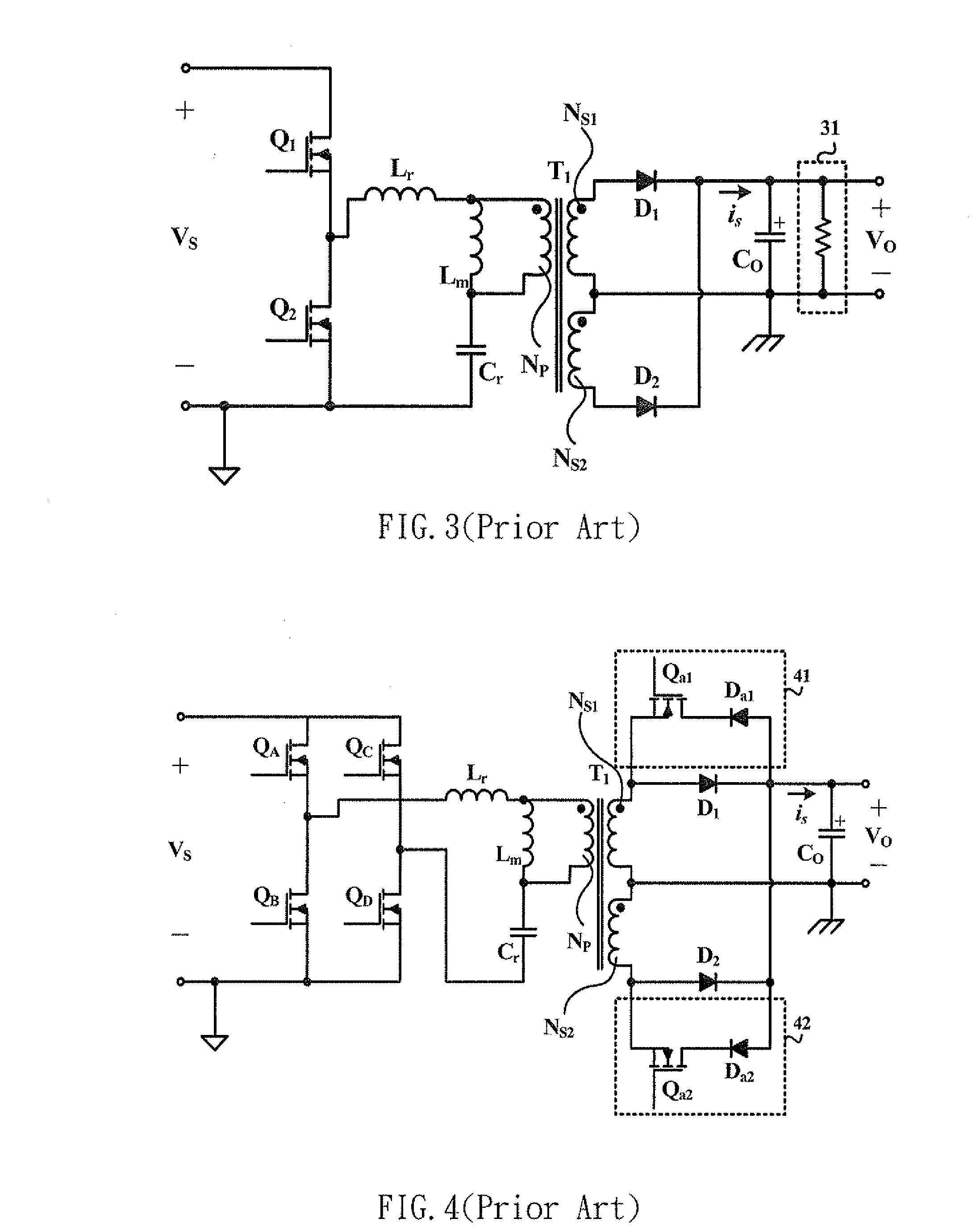
Nonetheless, this approach compromises the power conversion efficiency of the LLC resonant power converter and, because of the dummy resistor 31, causes high power consumption under light load (e.g., in the standby state).
In view of the above, the reason why the conventional LLC resonant power converter cannot effectively regulate its output voltage Vo under light load is that the parasitic capacitance of the primary winding and the parasitic capacitances of the two rectifiers on the secondary side are bound to resonate with the resonant inductor Lr in the moment when the power switches are switched, thereby causing accumulation of excessive energy in the parasitic capacitances.
Consequently, not only are the overall circuit complexity and production cost of the LLC resonant power converter significantly increased, but also the additional computation data and procedures must result in propagation delay of the related control signals, making it impossible for the secondary recharging circuits 41 and 42 to recharge the primary side in real time with the excessive energy received.
As such, effective regulation of the output voltage Vo under light load is unattainable after all.

Method used


Image

  • Llc resonant power converter with current-circulating circuit for enabling light-load regulation
  • Llc resonant power converter with current-circulating circuit for enabling light-load regulation
  • Llc resonant power converter with current-circulating circuit for enabling light-load regulation

Examples


Embodiment Construction

[0023]The first preferred embodiment of the present invention provides an LLC resonant power converter having a current-circulating circuit for enabling light-load regulation as shown in FIG. 5. This resonant power converter includes a half-bridge circuit 52, a resonant inductor Lr, a resonant capacitor Cr, a current-circulating circuit 51, a transformer T1, and a full-wave rectification circuit 53. The half-bridge circuit 52 is composed of a first power switch Q1 and a second power switch Q2 connected in series and is connected in parallel to an input voltage Vs. The gate of each of the first power switch Q1 and the second power switch Q2 is connected to the corresponding control pin of a resonant control chip (not shown). The drain of the first power switch Q1 is connected to the positive terminal of the input voltage Vs. The source of the first power switch Q1 is connected to the drain of the second power switch Q2. The source of the second power switch Q2 is connected to the neg...


PUM


Abstract

The present invention is to provide a power converter, which includes a half-bridge circuit parallel-connected to an input voltage and having two series-connected power switches, an LLC resonant circuit formed by a resonant inductor, magnetic inductance of a primary winding and a resonant capacitor, a current-circulating circuit parallel-connected to the half-bridge circuit and having two series-connected rectifiers, and a full-wave rectification circuit connected to a secondary winding for generating an output voltage across an output capacitor. The LLC resonant circuit is parallel-connected to one of the power switches, and the line between the two rectifiers is cross-connected to the line between the resonant inductor and the primary winding. Thus, since the current-circulating circuit is able to guide current through the resonant inductor into circulation in switching moment of the power switches, parasitic capacitance of the primary winding is prevented from being overcharged by the current through the resonant inductor accordingly.

Description

FIELD OF THE INVENTION[0001]The present invention relates to an LLC resonant power converter, more particularly to an LLC resonant power converter having a current-circulating circuit for enabling light-load regulation, which utilizes an LLC resonant circuit to smoothly receive energy transferred from an input voltage, and utilizes the current-circulating circuit to guide current through a resonant inductor of the LLC resonant power converter into circulation in switching moment of power switches of the LLC resonant power converter, thereby parasitic capacitance of primary winding of the LLC resonant power converter is prevented from resonating with the resonant inductor and hence from being overcharged, either forwardly or reversely, by the current through the resonant inductor. Thus, neither secondary winding nor output capacitor of the LLC resonant power converter will have spike currents, so as to effectively maintain output voltage of the LLC resonant power converter in a certa...

Claims


Application Information

Patent Timeline
IPC IPC(8): H02M3/335
CPCH02M3/3382H02M1/0032Y02B70/10
Inventor LIANG, JIM-HUNGCHEN, CHING-CHUAN
Owner SKYNET ELECTRONICS
Learn More