Method of refueling a nuclear reactor

a nuclear reactor and refueling technology, applied in nuclear engineering, nuclear elements, greenhouse gas reduction, etc., can solve the problems of affecting the operation of light water reactors, requiring periodic outages, and requiring careful attention to avoid damage or unnecessary radiation exposure, and traditional methods of refueling from being applied directly

Active Publication Date: 2013-11-07
WESTINGHOUSE ELECTRIC CORP
View PDF3 Cites 18 Cited by
  • Summary
  • Abstract
  • Description
  • Claims
  • Application Information

AI Technical Summary

Benefits of technology

[0013]Preferably, the step of raising the level of reactor coolant is accomplished with an existing reactor vessel penetration and the cylindrical tank is sealed to the reactor vessel flange.

Problems solved by technology

Nuclear power plants which employ light water reactors require periodic outages for refueling of the reactor.
Furthermore, the plant equipment and fuel assemblies are expensive and care must be taken not to cause damage or unnecessary radiation exposure due to improper handling of the fuel assemblies or fuel transfer equipment.
The physical configuration of some pressurized water reactor designs, including an integral reactor being developed for small modular reactor plants, prevents this traditional approach to refueling from being applied directly.

Method used


Image

  • Method of refueling a nuclear reactor
  • Method of refueling a nuclear reactor
  • Method of refueling a nuclear reactor

Examples


Embodiment Construction

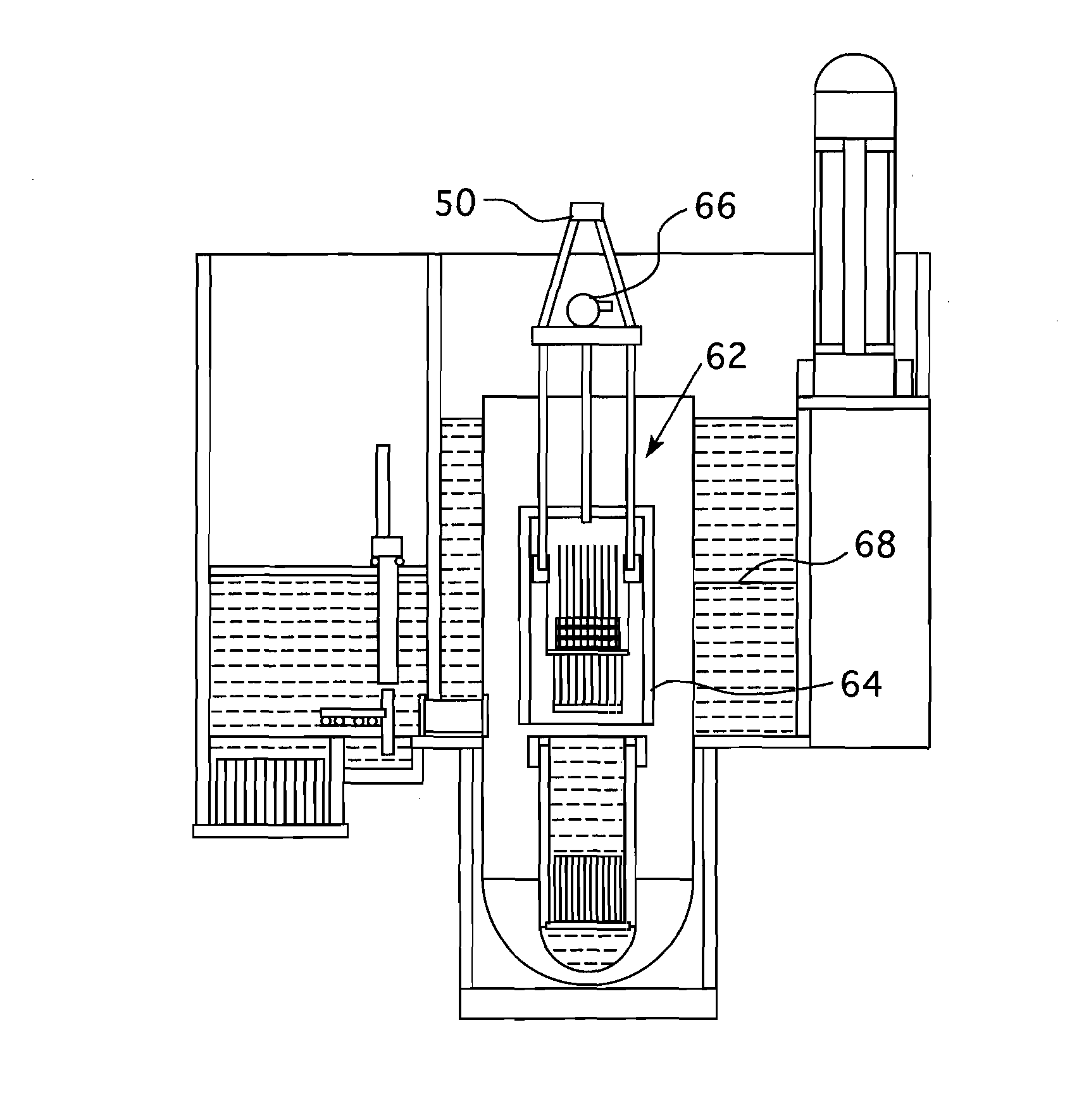
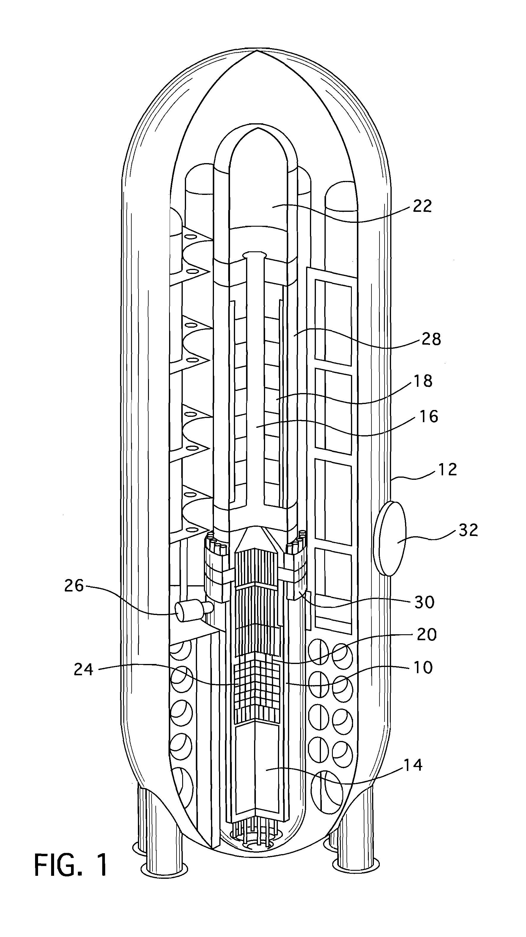
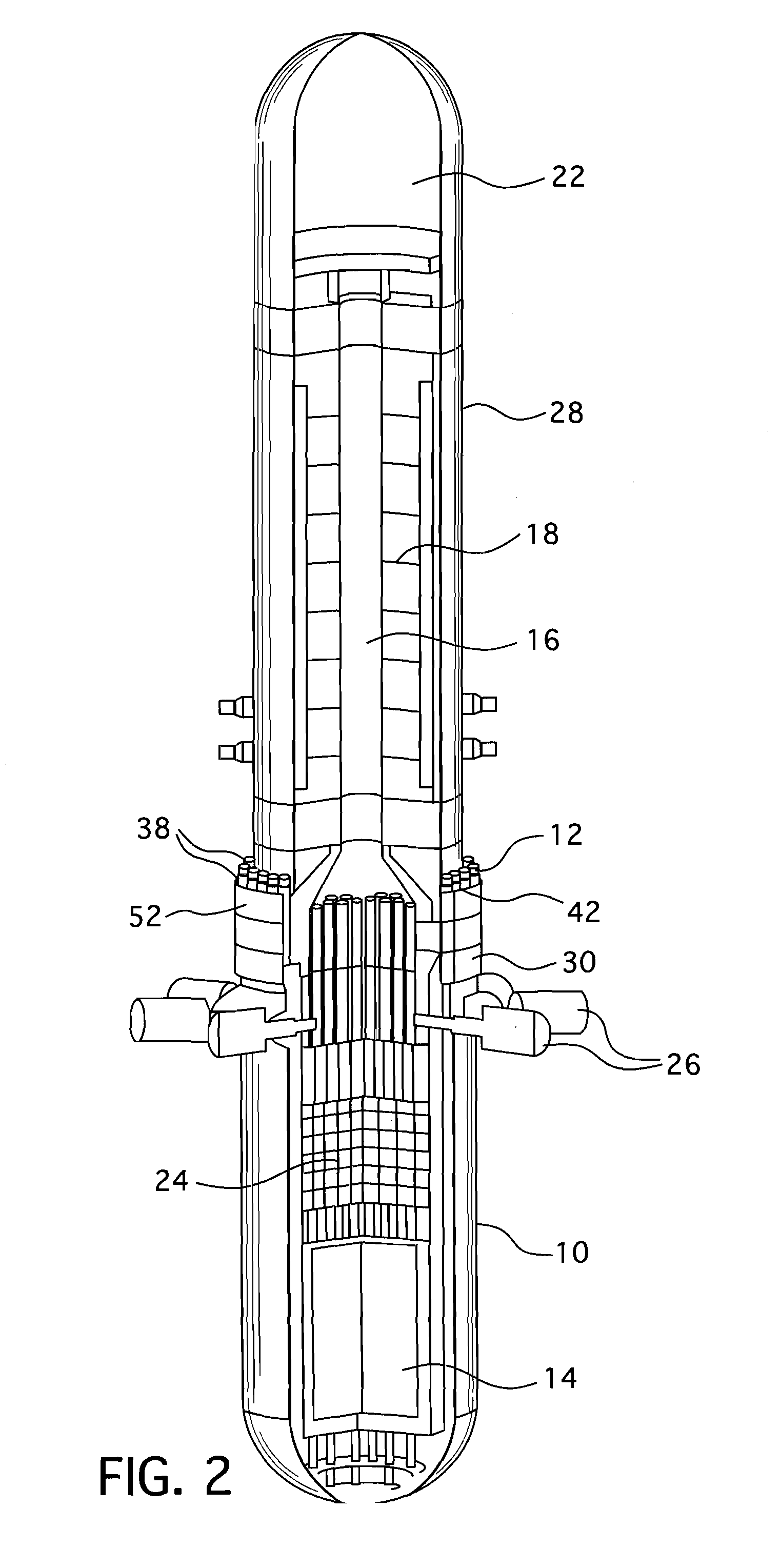
[0018]The steps of this embodiment are sequentially illustrated in FIGS. 3-14. This embodiment uses a temporarily installed refueling machine 36 attached directly to the reactor vessel 10. The machine 36 can use the reactor vessel stud holes 38 or a similar feature to secure and align itself to the reactor vessel 10. The machine preferably includes a shielded tank 40 that is open at the top and bottom. The tank seals to the flange 30 of the reactor 10 by contacting the mating surface of the vessel. An O-ring or similar soft seal can be used to limit leakage. Pressure applied to make the seal is either provided by the weight of the tank or by mechanical fasteners such as the studs 42. Any leakage would be detected by the existing reactor vessel leak-off lines provided between the O-ring seals used to seal the reactor vessel during plant operation. The tank 40 has a penetration 44 perpendicular to the center line of the tank. This penetration provides a means of transferring the fuel ...


PUM


Abstract

A method of refueling a nuclear reactor that includes the steps of removing the reactor vessel head and upper internals to a storage location and installing a cylindrical tank having open upper and lower ends, on the reactor vessel flange. The cylindrical tank is sealed to the reactor vessel and a penetration on the side of the cylindrical tank is sealed to a refueling canal that is connected to a spent fuel pool. The level of reactor coolant within the reactor vessel is then raised to at least partially fill the cylindrical tank to a level equal to that of the spent fuel pool. The refueling canal is then opened and a refueling machine supported on the reactor vessel is employed to transfer fuel assemblies between the core and the spent fuel pool.

Description

BACKGROUND[0001]1. Field[0002]This invention relates generally to a method for refueling a nuclear reactor, and in particular, to a method of refueling a small modular reactor with a compact containment vessel.[0003]2. Related Art[0004]Nuclear power plants which employ light water reactors require periodic outages for refueling of the reactor. New fuel assemblies are delivered to the plant and are temporarily stored in a fuel storage building, along with used fuel assemblies which may have been previously removed from the reactor. During a refueling outage, a portion of the fuel assemblies in the reactor are removed from the reactor to the fuel storage building. A second portion of the fuel assemblies are moved from one support location in the reactor to another core support location in the reactor. New fuel assemblies are moved from the fuel storage building into the reactor to replace those fuel assemblies which were removed. These movements are done in accordance with a detailed ...

Claims


Application Information

Patent Timeline
Patent Type & Authority Applications(United States)
IPC IPC(8): G21C19/20
CPCG21C11/022G21C19/20G21F7/015Y02E30/30G21C19/00
Inventor HARKNESS, ALEXANDER W.CUMMINS, WILLIAM EDWARD
Owner WESTINGHOUSE ELECTRIC CORP
Why Eureka
Try Eureka