Tire detection for accurate vehicle speed estimation

a technology of accurate vehicle speed estimation and tire detection, which is applied in the direction of time traversed devices, image analysis, instruments, etc., can solve the problems of no standard vehicle feature that is fixed height, speed calculated by analyzing non-stereo images taken of moving vehicles, and lack of accuracy required for law enforcemen

Active Publication Date: 2013-11-07
CONDUENT BUSINESS SERVICES LLC
View PDF2 Cites 64 Cited by
  • Summary
  • Abstract
  • Description
  • Claims
  • Application Information

AI Technical Summary

Benefits of technology

[0007]In accordance with some aspects of the present disclosure, a computer-implemented method for determining the speed of a motor vehicle in a vehicle speed detection system is disclosed. The method can comprise receiving a plurality of images of a motor vehicle traveling on a road, each of the images being separated in time by a known interval; determining, for each of at least two of the images, a point of contact where a same tire of the vehicle contacts a surface of the road based, in part, on one or more identified features of the vehicle in one or more of the plurality of images; and using the points of contact and the time interval separations to calculate a speed at which the vehicle is traveling on the road.

Problems solved by technology

Unfortunately, vehicle features are not placed at fixed heights across all vehicle makes and models.
Unfortunately, there is no standard vehicle feature that is at a fixed height for vehicles of all types, makes and models.
As such, speeds calculated by analyzing non-stereo images taken of moving vehicles tend to lack the accuracy required for law enforcement.
The challenge to this is the detection reliability, as the contrast between the tires and the pavement is typically very low, because both materials exhibit high absorbances at visible or near-IR wavelengths.
This problem is further complicated by shadows in the region of interest.
This may enhance the image contrast; however, the camera system required is non-conventional and would likely be costly.

Method used


Image

  • Tire detection for accurate vehicle speed estimation
  • Tire detection for accurate vehicle speed estimation
  • Tire detection for accurate vehicle speed estimation

Examples


Embodiment Construction

[0039]Reference will now be made in detail to various exemplary embodiments of the present application, examples of which are illustrated in the accompanying drawings. Wherever possible, the same reference numbers will be used throughout the drawings to refer to the same or like parts.

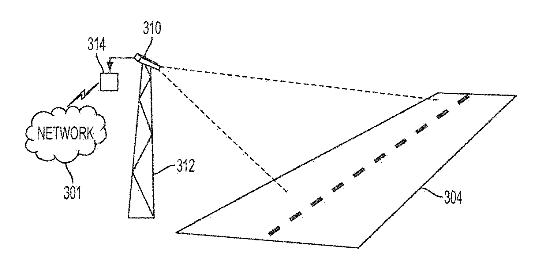
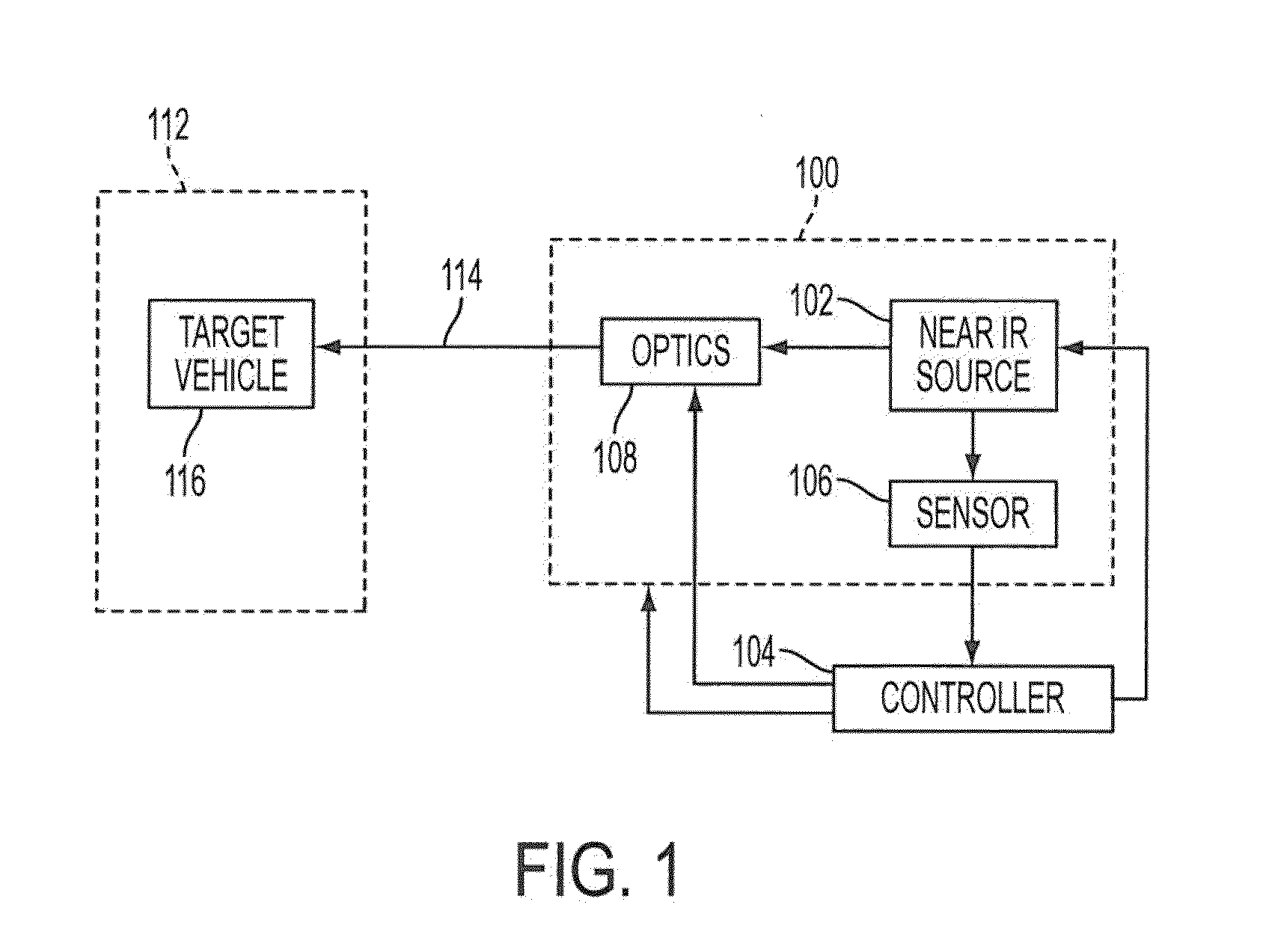
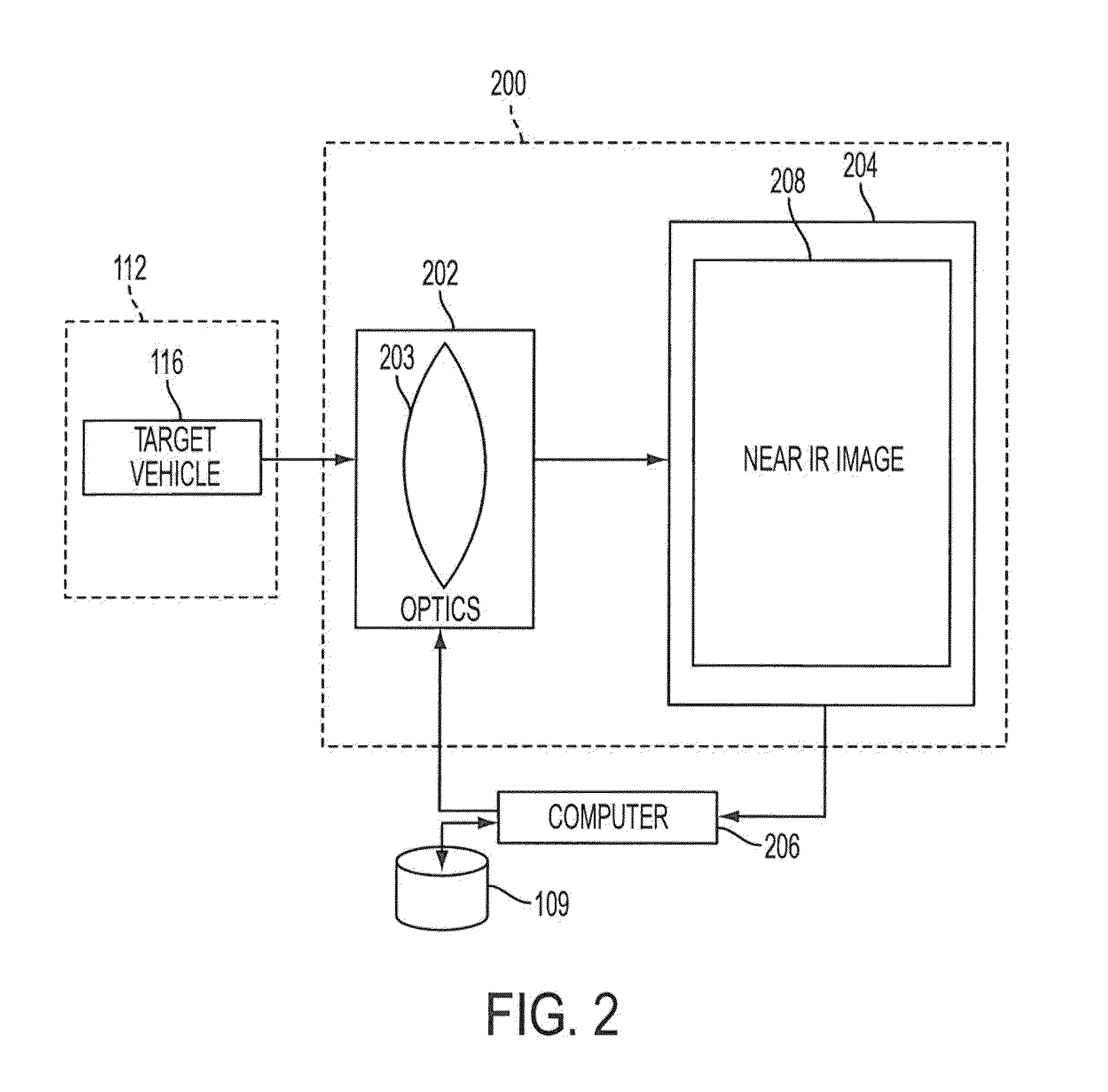
[0040]What is disclosed is a system and method which detects and uses a point of contact between a vehicle's tire and the road surface for accurate speed detection. The present method uses an image algorithm to detect the interface between tire and asphalt for contact-point detection thus reducing the above-described problem with respect to feature height variation across vehicles to a “zero height” thereby eliminating the trigonometric calculations for height correction altogether. In some aspects, the system and method can use NIR (Near IR) and / or visual light. For example, but not limited to, NIR bands that can be use include bands such as 780 nm, or 850 nm. The use of NIR, in combination with or se...


PUM


Abstract

In some aspects of the present application, a computer-implemented method for determining the speed of a motor vehicle in a vehicle speed detection system is disclosed. The method can include receiving a plurality of images of a motor vehicle traveling on a road, each of the images being separated in time by a known interval; determining, for each of at least two of the images, a point of contact where a same tire of the vehicle contacts a surface of the road based, in part, on one or more identified features of the vehicle in one or more of the plurality of images; and using the points of contact and the time interval separations to calculate a speed at which the vehicle is traveling on the road.

Description

FIELD OF THE DISCLOSURE [0001]The present application is directed to systems and methods for determining a speed of a vehicle by tracking vehicle features in a sequence of images captured over a known time interval or frame rate.BACKGROUND OF THE DISCLOSURE [0002]Methods for vehicle speed detection using video have many important transportation applications. For applications such as traffic speed enforcement, accurate speed detection is necessary. One method for determining a vehicle's speed is to capture two time-sequenced images of that vehicle, track a specific feature on that vehicle such as, for example, a location of the vehicle's license plate, and then calculate the vehicle's speed from trigonometric relationships. For accurate speed determination, the precise height above the road surface of the feature being tracked needs to be known in advanced, unless a stereo imaging system is used, wherein pairs of images from two different positions are captured. Unfortunately, vehicl...

Claims


Application Information

Patent Timeline
Patent Type & Authority Applications(United States)
IPC IPC(8): G06K9/00
CPCG01P3/38G01P3/68G06T7/246G06T7/50G06T7/74G06T2207/10016G06T2207/30236G06T2207/30241
Inventor FAN, ZHIGANGWU, WENCHENG
Owner CONDUENT BUSINESS SERVICES LLC
Why Eureka
Try Eureka