Helical drill bit for an auger of a ground excavation assembly, in particular for building excavated piles, and drilling method that uses such a bit

Active Publication Date: 2013-11-07
SOILMEC
View PDF11 Cites 11 Cited by
  • Summary
  • Abstract
  • Description
  • Claims
  • Application Information

AI Technical Summary

Benefits of technology

[0057]In particular, by using a bit and a drilling method according to the present invention, it is possible to make a drilling the diameter of which is substantially the same along the whole extension of its longitudinal axis, in other words in the section of piped

Problems solved by technology

However, the fact that such equipment has a single trolley 3 has the drawback that it is net possible to leave the casing pipe 10 in the excavated hole without disconnecting it from the lower drive head 4i.
This operation requires costly time and procedures.
Moreover, the overall structure of such equipment is in any case simpler and more effective than the variant described in FIG. 1, having sliding devices 6 acting directly between tube and upper drive head (to limit the heights of such sliding devices that could otherwise be problematic in the case of restricted spaces or for transportation, it would be necessary to carry out many shorter travels and a multiplicity of grippings that would reduce its effectiveness and would complicate its control).
The problems due to the aforementioned difference in diameters are particularly, but not only, great in the case of barriers or partitions formed from intersecting piles.
However, this provision involves taking longer to make the piles, greater consumption of concrete, a greater amount of primary piles to be demolished when the secondary piles are made.
This in turn leads to a substantial increase in production costs, which raises substantial economic problems and considerations in making barr

Method used


Image

  • Helical drill bit for an auger of a ground excavation assembly, in particular for building excavated piles, and drilling method that uses such a bit
  • Helical drill bit for an auger of a ground excavation assembly, in particular for building excavated piles, and drilling method that uses such a bit
  • Helical drill bit for an auger of a ground excavation assembly, in particular for building excavated piles, and drilling method that uses such a bit

Examples


Embodiment Construction

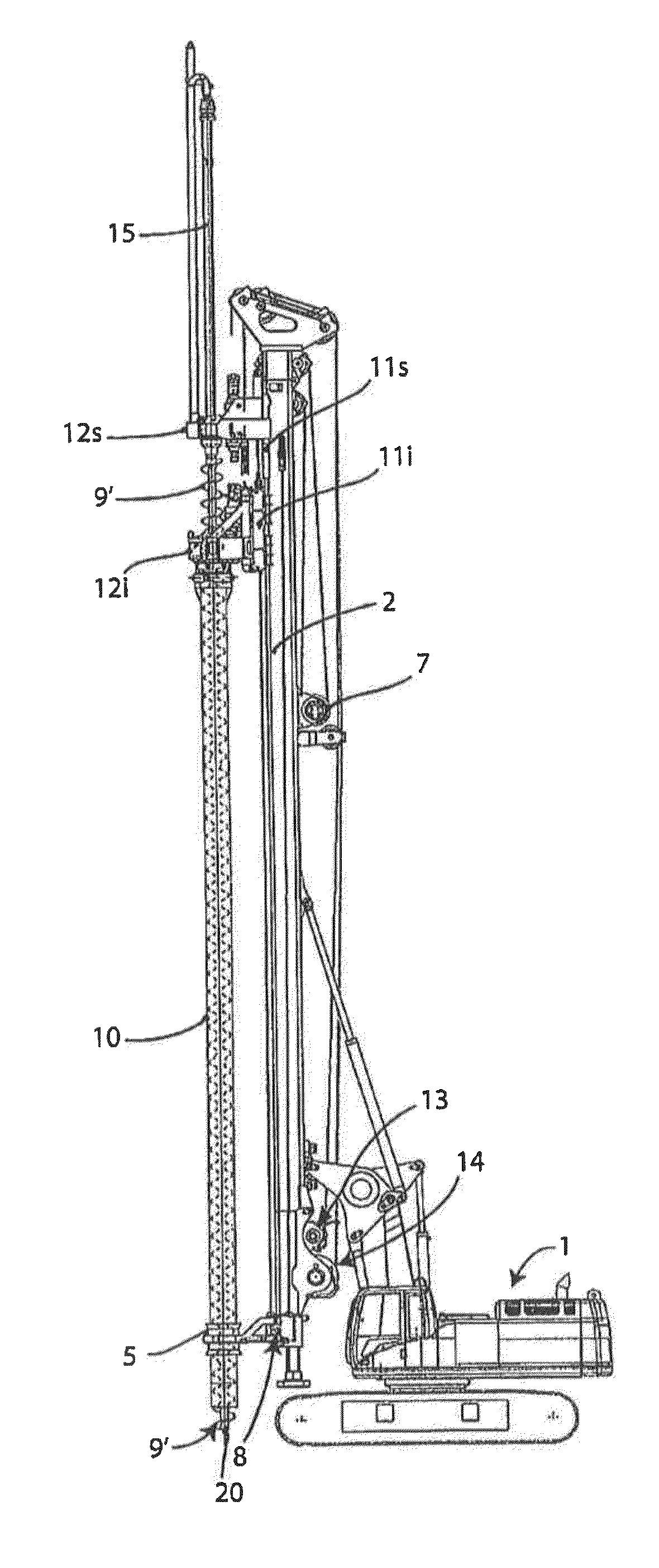
[0070]With reference to FIG. 5, an example of drilling equipment including a drilling tool equipped with an example embodiment of a bit according to the present invention is illustrated. Such a tool is wholly indicated with 9′ to distinguish it from the drilling tools illustrated in combination with the equipment of the previous figures and made according to the prior art.

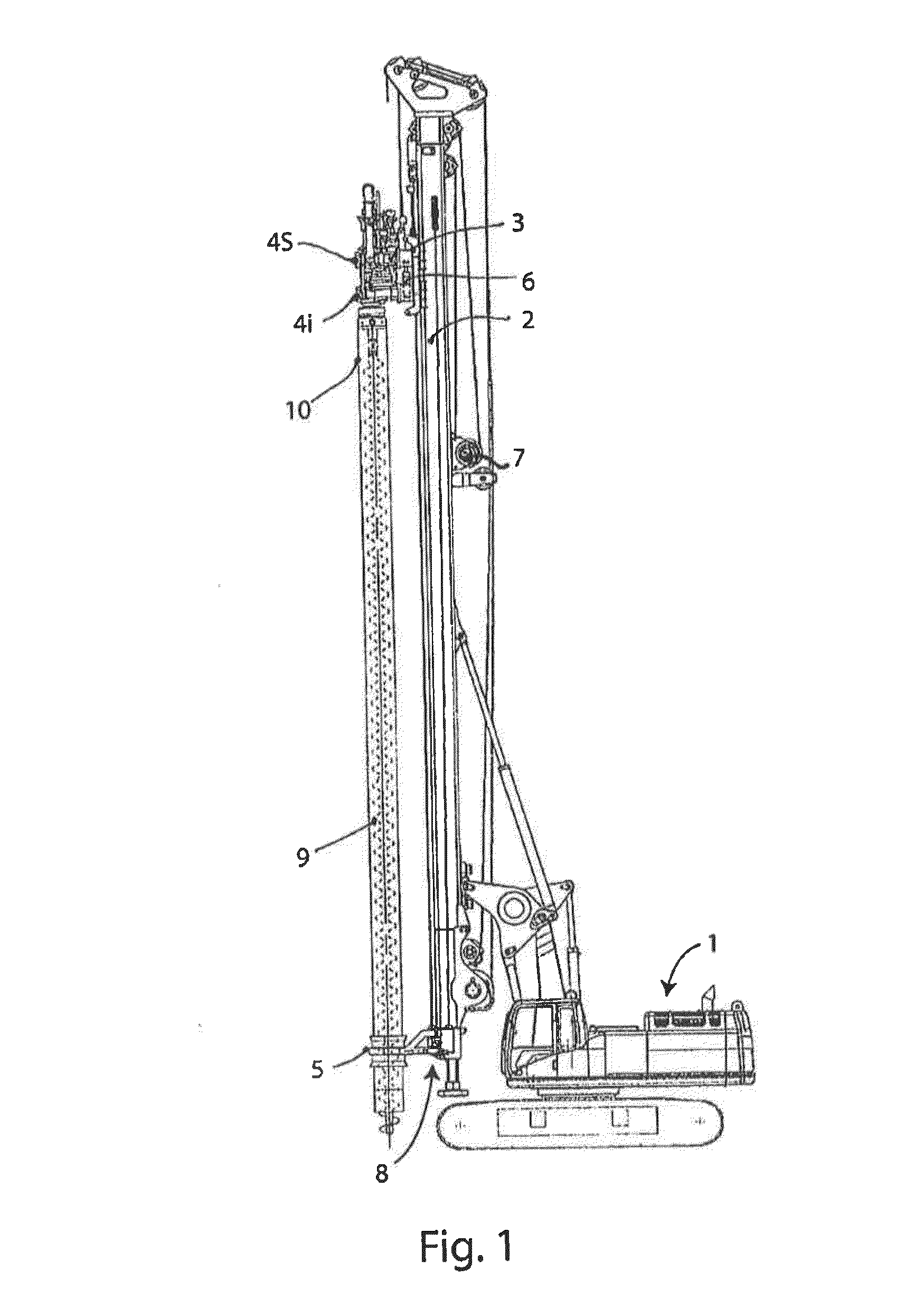
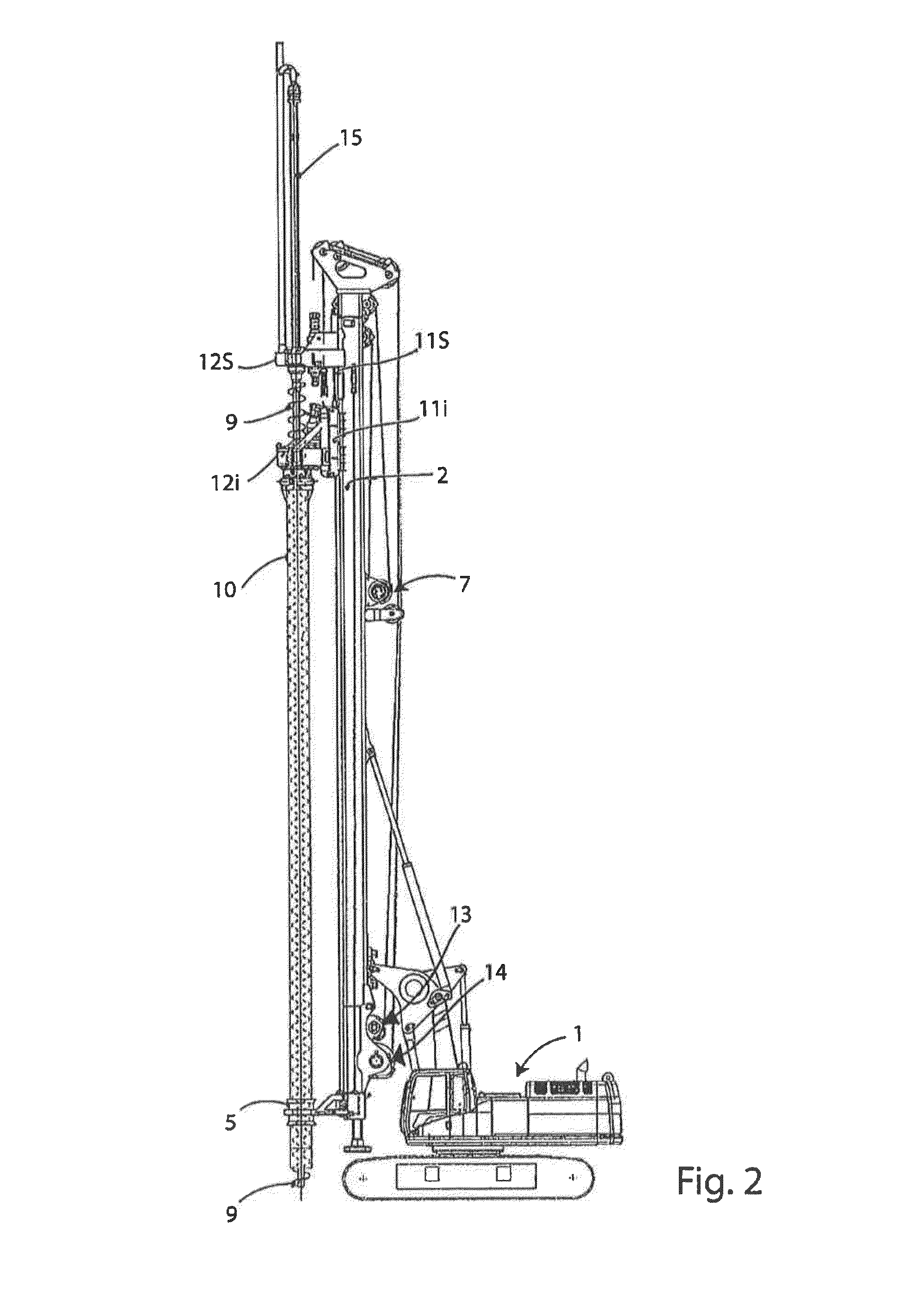
[0071]Details and elements that are similar—or having an analogous function—to those of the example of equipment made according to the prior art and illustrated in FIGS. 2 to 4, have the same alphanumeric references associated with them. In order to be brief, the description of such details and elements will not be repeated again hereafter, but we refer to what has been quoted earlier in the presentation of the technological background relative to the present invention.

[0072]As a whole, the drilling tool or auger 9′ defines a helical or Archimedean screw-type structure extending cylindrically around a longitudinal ...


PUM


Abstract

The helical drill bit defines a helical end section of a helical structure formed at its periphery by an auger of an excavation assembly, and it is associated or associate with a support portion of the auger. Such a support portion defines a proximal section of the helical structure, which has an extension substantially centred around a longitudinal axis (X-X). The helical drill bit is adapted to rotate about the longitudinal axis (X-X) together with the support portion so as to drill a hole in the ground. The helical end section extends around an extremity axis (Y-Y; Ψ-Ψ) that is not aligned relative to the longitudinal axis (X-X).

Description

CROSS REFERENCE TO RELATED APPLICATION[0001]This patent application claims the benefit of Italian Patent Application. No. TO2012A 000405, filed May 7, 2012, the entire contents of which are incorporated herein by reference.DESCRIPTION[0002]1. Technical Field[0003]The present invention concerns a helical drill bit for an auger of a ground excavation assembly, in particular for building excavated piles, and a drilling method that uses such a bit.[0004]More specifically, the present invention refers to a helical drill bit made according to the preamble of the attached claim 1, and to a drilling method carried out with the aforementioned helical drill bit.[0005]2. Technological Background[0006]The present invention thus fits into the technological field of foundations in which, for almost twenty years, the technique of the so-called pile excavated with a continuous auger, partially or totally piped, has been known. In particular, for building excavated piles equipment is generally used ...

Claims


Application Information

Patent Timeline
IPC IPC(8): E02D7/30E21B10/44
CPCE02D7/30E21B10/44E21B7/005E21B10/26E21B17/12
Inventor BISERNA, EZIOVANNI, DANIELE
Owner SOILMEC
Why Eureka
Try Eureka