

Yaw-rate sensor
a sensor and yaw rate technology, applied in the field of yaw rate sensors, can solve the problems of unintentional deflection of the partial oscillator, false signals, and high susceptibility to interference, and achieve the effect of avoiding interference signals
- Summary
- Abstract
- Description
- Claims
- Application Information
AI Technical Summary
Benefits of technology
Problems solved by technology
Method used
Image

Examples
Embodiment Construction
[0029]Identical parts are provided with the same reference numerals in the various figures, and therefore generally are in each case designated or mentioned only once, as well.
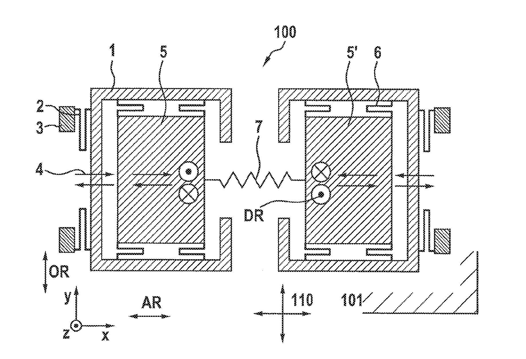
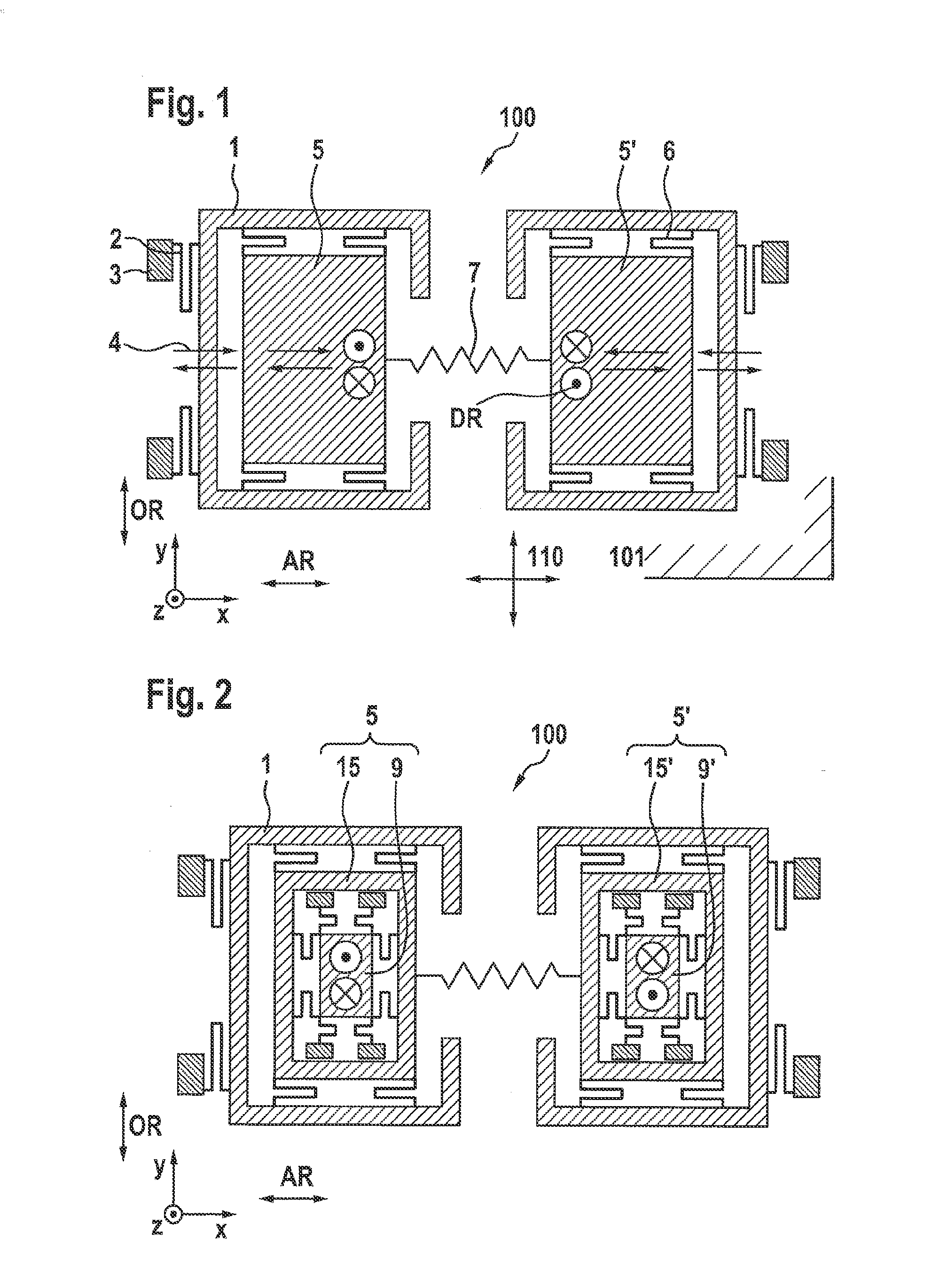
[0030]FIGS. 1 and 2 each show schematic diagrams of conventional, especially micromechanically produced, yaw-rate sensors 100 which are provided to detect yaw rates about a first direction OR (in the example of a Ωy-sensor in FIGS. 1 and 2, this corresponds to the y-axis), and which are realized on a substrate 101 that has a main extension plane 110 and pre-defines it for the sensor or yaw-rate sensor, as well. Substrate 101 and main extension plane 110 are drawn in only in FIG. 1, however are likewise present in the case of all FIGS. 1, 2, as well as 4 through 23, since all these figures depict top views of the sensor structures, that is, the drawing plane corresponds to main extension plane 110. Such yaw-rate sensors include two oscillatory masses (partial oscillators) which are driven to an antiparallel mod...
PUM
 Abstract
Description
Claims
Application Information