Prediction and diagnosis of lost circulation in wells

a technology of lost circulation and wells, applied in the field of prediction and diagnosis of lost circulation in wells, can solve the problems of reducing the counter balance effect, reducing the cost of unit mud costs, and excessive loss of drilling fluid

Inactive Publication Date: 2013-11-14
BP CORP NORTH AMERICA INC +1
View PDF4 Cites 55 Cited by
  • Summary
  • Abstract
  • Description
  • Claims
  • Application Information

AI Technical Summary

Problems solved by technology

While it is normal to lose some drilling fluid in the circulation process, excessive lost drilling fluid is expensive in terms of unit mud costs (especially whole synthetic or low toxicity mineral oil mud) and non-productive time.
It may pose safety related concerns, as drilling fluid is bulky, difficult to mix, difficult to store and excessive losses may reduce the counter balance effect against formation fluids.

Method used


Image

  • Prediction and diagnosis of lost circulation in wells
  • Prediction and diagnosis of lost circulation in wells
  • Prediction and diagnosis of lost circulation in wells

Examples


Embodiment Construction

[0016]This disclosure proceeds as follows. Section I discusses causes of drilling fluid lost circulation events. Section II discusses observable physical parameters, and tools for their measurement, that affect drilling fluid circulation losses. Section III discusses correlating the observable parameters to drilling fluid lost circulation event causes. Section IV discusses remedies for the different types of drilling fluid lost circulation event causes.

I. Drilling Fluid Lost Circulation Event Causes

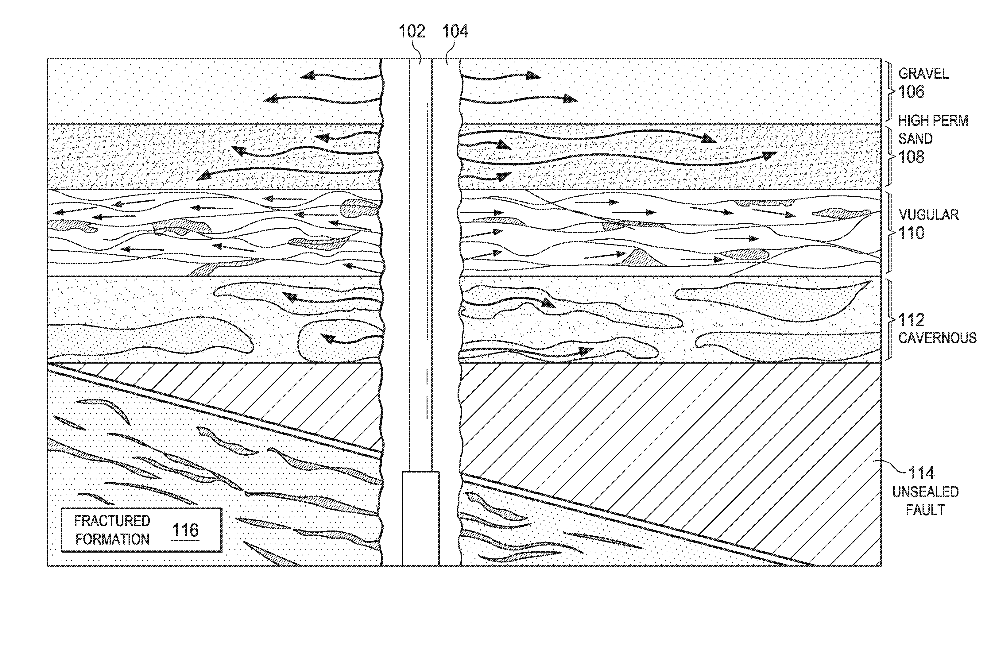
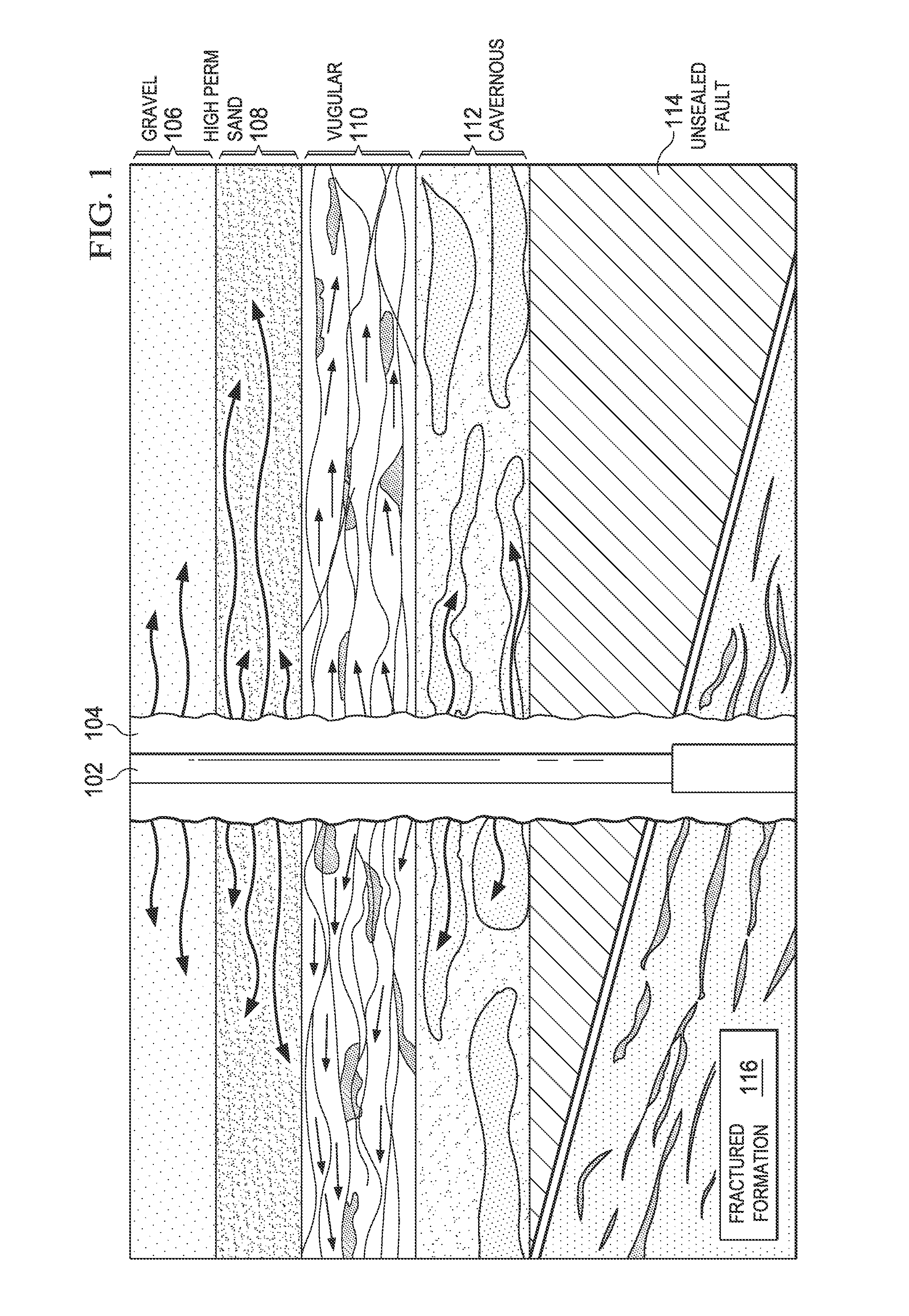
[0017]FIG. 1 is a schematic diagram representing several types of drilling fluid lost circulation causes. In particular, FIG. 1 depicts drill string 102 in borehole 104. Represented schematically are several types of formations 106-116 that may cause drilling fluid circulation loss.

[0018]Drilling fluid circulation loss may occur via seepage into porous material such as gravel 106 and certain types of sand, e.g., high permeability sand 108. Drilling fluid may be lost within the matrix perm...


PUM


Abstract

In accordance with aspects of the present disclosure, techniques for predicting, classifying, preventing, and remedying drilling fluid circulation loss events are disclosed. Tools for gathering relevant data are disclosed, and techniques for interpreting the resultant data as giving rise to an actual or potential drilling fluid lost circulation event are also disclosed.

Description

CROSS-REFERENCE TO RELATED APPLICATIONS[0001]Not applicable.STATEMENT REGARDING FEDERALLY SPONSORED RESEARCH OR DEVELOPMENT[0002]Not applicable.BACKGROUND[0003]Drilling boreholes (e.g., for oil or natural gas wells) sometimes includes the use of drilling fluid, also known as “drilling mud.” Drilling fluid serves to provide counter- pressure against formation pressure as well as to lubricate the drill bit and carry cuttings for hole cleaning. Drilling fluid is typically pumped from a surface mud tank (or “mud pit”) down the drill pipe, so as to exit the drill bit at the end of the drill string. There, it provides its lubrication, sealing and cleaning functions. Thereafter, the drilling fluid flows up the annulus of the drill string and back to the surface. At the surface, the drilling fluid is cleaned of debris and returned to the reservoir, where it is re-used. Thus, drilling fluid flows in a loop, from the surface, to the bottom of the borehole, and back. This flow is referred to a...

Claims


Application Information

Patent Timeline
Patent Type & Authority Applications(United States)
IPC IPC(8): E21B47/10
CPCE21B44/00E21B21/003E21B47/10
Inventor ALBERTY, MARK WILLIAMASTON, MARKROJAS, JUAN CARLOSSANT, RANDALLZHANG, JIANGUO
Owner BP CORP NORTH AMERICA INC
Why Eureka
Try Eureka