Motor controller and electric power steering device using the same

a technology which is applied in the direction of electric generator control, dynamo-electric converter control, dynamo-electric gear control, etc., can solve the problems of difficult downsizing of motor controller and electric steering device, the possibility of motor controller controlling a polyphase motor, and the increase in the number of components, etc., to achieve suppressed pulsation, low cost, and simple configuration

Active Publication Date: 2013-11-14
MITSUBISHI ELECTRIC CORP
View PDF7 Cites 61 Cited by
  • Summary
  • Abstract
  • Description
  • Claims
  • Application Information

AI Technical Summary

Benefits of technology

[0012]Further, there is no possibility that a harmful torque such as a torque pulsation is generated in the faulty s...

Problems solved by technology

As described above, a motor controller for controlling a polyphase motor has a possibility of occurrence of the following faults as faults which may occur in the windings or the inverters of the motor.
Therefore, in the case of some fault, there is a possibility that an ove...

Method used


Image

  • Motor controller and electric power steering device using the same
  • Motor controller and electric power steering device using the same
  • Motor controller and electric power steering device using the same

Examples


first embodiment

[0019]Hereinafter a first embodiment of the present invention is described in detail referring to the accompanying drawings.

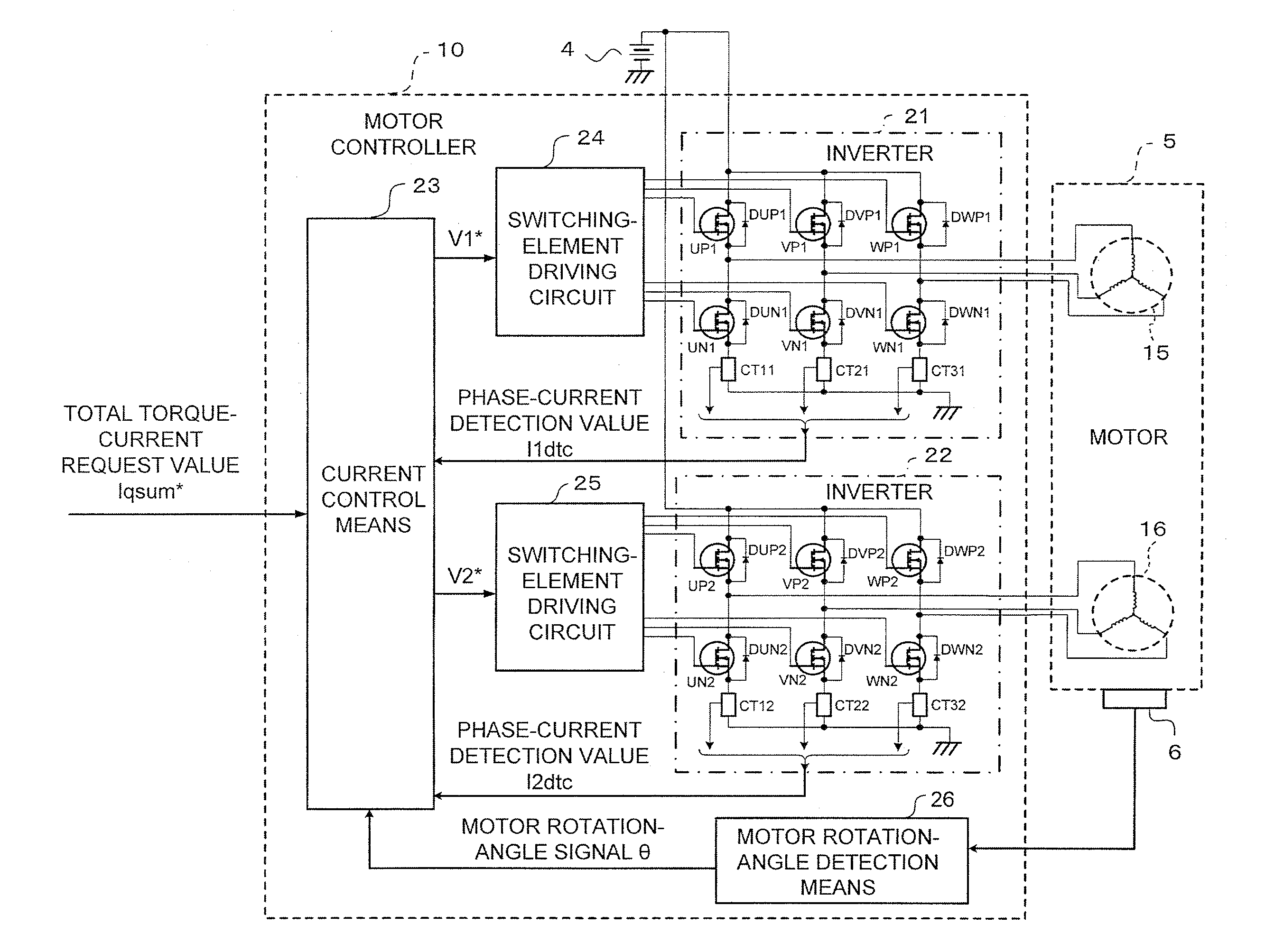
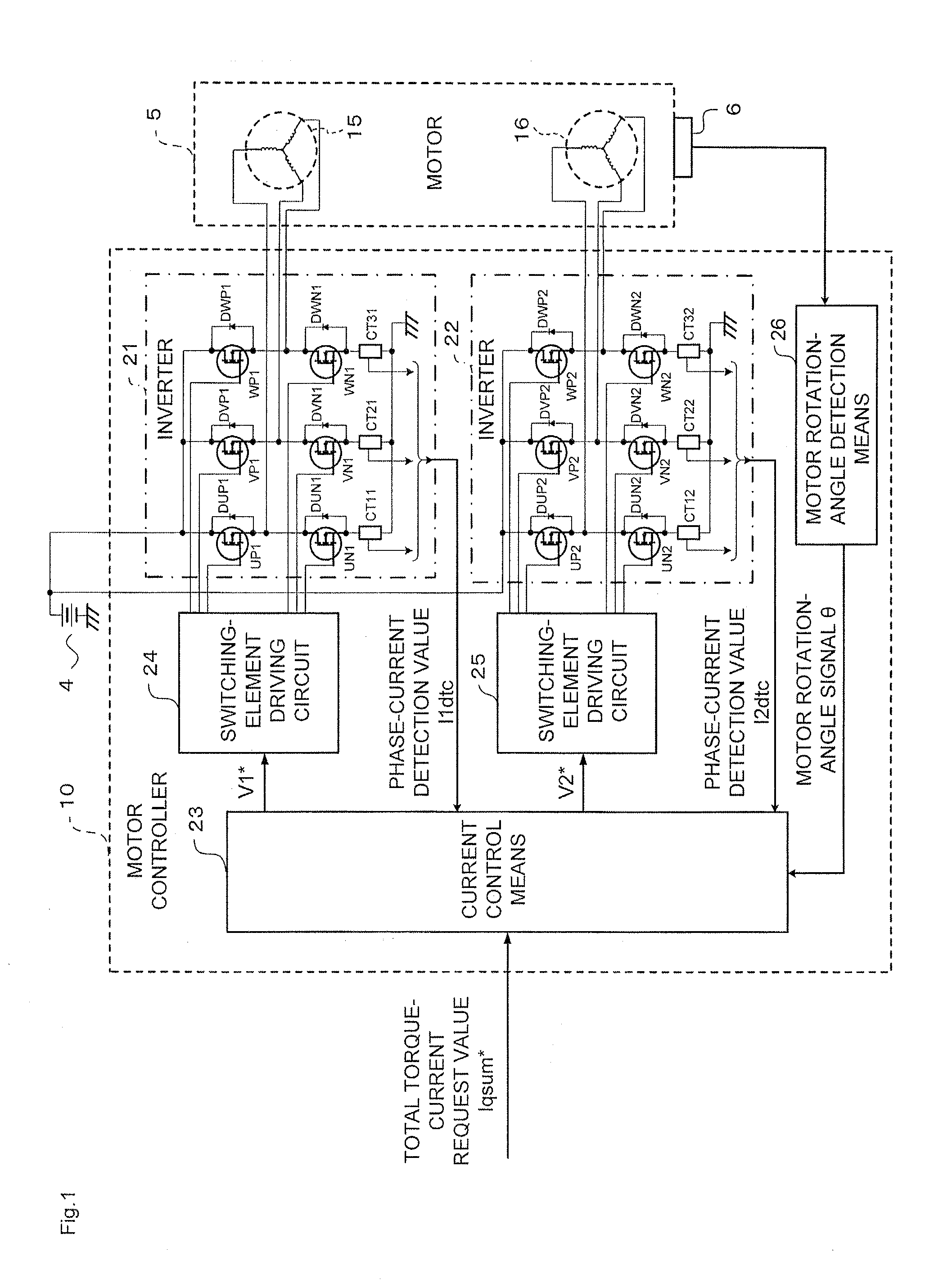
[0020]FIG. 1 is a block diagram schematically illustrating an overall configuration of a motor controller 10 according to the first embodiment of the present invention.

[0021]FIG. 1 illustrates not only the motor controller 10 but also a peripheral configuration relating to the motor controller 10. Specifically, the peripheral configuration includes a power source 4 (for example, an in-vehicle battery), a motor 5, and a motor rotation-angle sensor 6 for detecting a rotation angle of the motor 5.

[0022]In FIG. 1, the motor 5 includes a first winding set 15 having three phases, that is, a U1-phase, a V1-phase, and a W1-phase, and a second winding set 16 having three phases, that is, a U2-phase, a V2-phase, and a W2-phase. Each of the winding sets 15 and 16 respectively corresponding to a first system and a second system is obtained by connecting the three phases in...

second embodiment

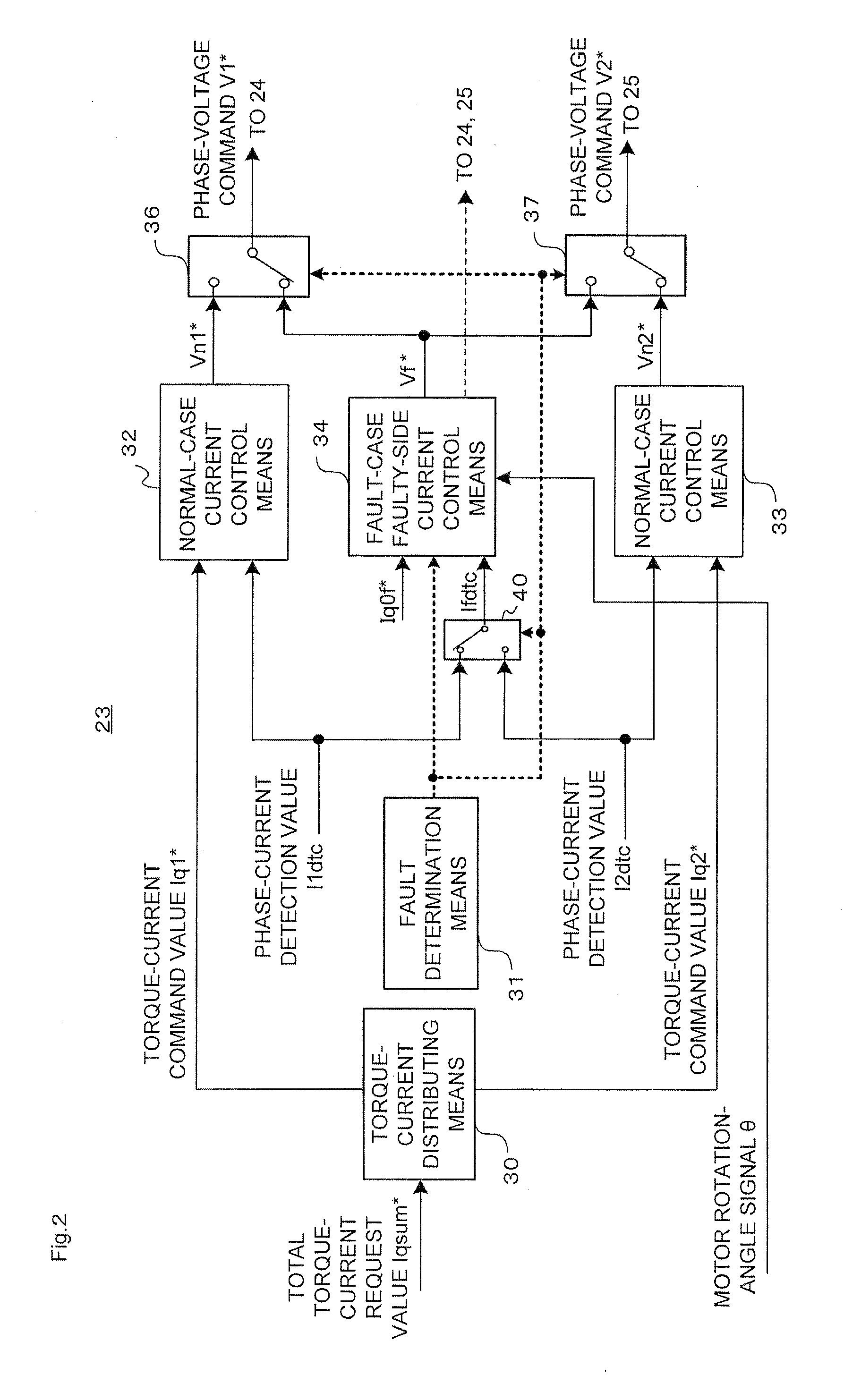
[0124]In the first embodiment (FIG. 2) described above, the currents in the normal winding driving system in the case of the fault are controlled by the normal-case current control means 32 and 33. However, as illustrated in FIG. 3, fault-case normal-side current control means 35 may be additionally provided so that the currents in the normal winding driving system in the case of a fault are controlled by the fault-case normal-side current control means 35 separately from the normal-case current control means 32 and 33 in a way different from the control for the normal operation.

[0125]FIG. 3 is a block diagram illustrating a functional configuration of current control means 23A according to a second embodiment of the present invention. The same components as those described above (see FIG. 2) are denoted by the same reference symbols or the same reference symbols followed by “A”, and the detailed description thereof is herein omitted.

[0126]The overall configuration of the motor cont...

third embodiment

[0184]Although not specifically referred to in the second embodiment (FIG. 3) described above, the fault-case normal-side current control means 35, which is included in the current control means 23A, may add a pulsating component at a low level or a high frequency to the current to be supplied to each of the windings of the normal winding driving system when a fault is detected by the fault determination means 31.

[0185]A third embodiment of the present invention, in which the pulsating component is added to the current to be supplied to each of the windings of the normal winding driving system, is hereinafter described referring to FIG. 3.

[0186]In this case, pulsation adding means for adding the pulsating component to the controlled current of the normal winding driving system can be provided, for example, in the fault-case normal-side current control means 35 of FIG. 3.

[0187]Specifically, in FIG. 3, a small pulsation at such a level as not to give a feeling of discomfort in steerin...


PUM


Abstract

Provided are a motor controller for suppressing a torque pulsation with a simple configuration and obtaining a sufficient output torque in the case of an open-type fault occurring in any one of windings of a motor and inverters, and an electric power steering device using the motor controller. In the motor controller for controlling a current supplied from and a voltage applied from a power source with respect to the motor including winding sets of a plurality of systems, when a fault determination unit (31) determines the occurrence of the open-type fault, the supply of the currents to the windings of one of the systems in which the fault has occurred is stopped by control performed on switching elements included in the inverter of the faulty system, whereas the supply of the currents to the windings of the normal system in which the fault has not occurred is continued.

Description

BACKGROUND OF THE INVENTION[0001]1. Field of the Invention[0002]The present invention relates to a motor controller for controlling a polyphase motor including a plurality of sets of windings and an electric power steering device using the motor controller.[0003]2. Description of the Related Art[0004]As a conventional electric power steering device, there is known an electric power steering device including, in a motor, two sets of windings, two inverters for controlling currents flowing through the respective winding sets, and individual power relays for supplying power from a power source to the respective inverters so that the current flowing through each of the winding sets is individually controllable (for example, see Japanese Patent Application Laid-open No. 2011-131860).[0005]The conventional electric power steering device described in Japanese Patent Application Laid-open No. 2011-131860 cited above is configured as follows. In the case of a fault in one of the winding sets...

Claims


Application Information

Patent Timeline
IPC IPC(8): H02P6/12B62D5/04H02P6/06H02P6/08H02P6/28H02P21/00H02P21/05H02P21/22H02P23/04H02P25/02H02P25/22H02P27/06H02P27/08
CPCH02P6/12B62D5/0463B62D5/0484B62D5/0409B62D5/046B62D5/0487
Inventor ENDO, MASAYAKEZOBO, ISAOKIMPARA, YOSHIHIKOOKADA, JIRO
Owner MITSUBISHI ELECTRIC CORP
Why Eureka
Try Eureka