
Acoustic structure with increased bandwidth suppression

a technology of acoustic structures and bandwidth, applied in the field of acoustic structures, can solve the problems of complex basic design problems, increased noise at lower frequencies, thin and lightweight nacelles, etc., and achieve the effects of low noise frequencies, increased effective resonator length, and increased bandwidth or acoustic range of nacelles or other types of acoustic structures

Active Publication Date: 2013-11-14
HEXCEL
View PDF3 Cites 30 Cited by
  • Summary
  • Abstract
  • Description
  • Claims
  • Application Information

AI Technical Summary

Benefits of technology

The present invention relates to a method for increasing the bandwidth or acoustical range of a nacelle or acoustic structure without increasing the thickness or weight of the structure. This is achieved by acoustically coupling honeycomb cells together to form pairs of acoustic cells that have an effective acoustic or resonator length that is up to twice that of either acoustic cell taken alone. The increased effective resonator length allows the structure to absorb relatively low noise frequencies without increasing the thickness or weight of the structure. Additionally, the invention provides a way to form acoustic cells having lengths that are smaller or greater than the thickness of the honeycomb, which increases the band with or range of frequencies that can be absorbed by the structure. This method is especially useful for jet engine nacelles where it is desirable to make the honeycomb as thin as possible while still providing effective resonators for dampening low-frequency jet engine noise.

Problems solved by technology

One particularly problematic noise source is the jet engine used on most passenger aircraft.
A basic problem facing acoustic engineers is to make the nacelle as thin and lightweight as possible while still providing adequate suppression or dampening of the sound wave frequencies over the entire range of noise generated by the jet engine.
This basic design problem is complicated by the fact that the trend in newer models of large jet engines is to produce additional noise at lower frequencies.
This results in the production of engine noise having a lower frequency.
However, this results in an increase in the size and weight of the nacelle which is contrary to the design goal of providing nacelles that are as thin and light weight as possible.
In addition, the increase in weight and size of the nacelle required to absorb low-frequency noise may be unacceptable, especially for larger aircraft engines where the size and weight of the nacelle is a major engineering design consideration.

Method used


Image

  • Acoustic structure with increased bandwidth suppression
  • Acoustic structure with increased bandwidth suppression
  • Acoustic structure with increased bandwidth suppression

Examples


Embodiment Construction

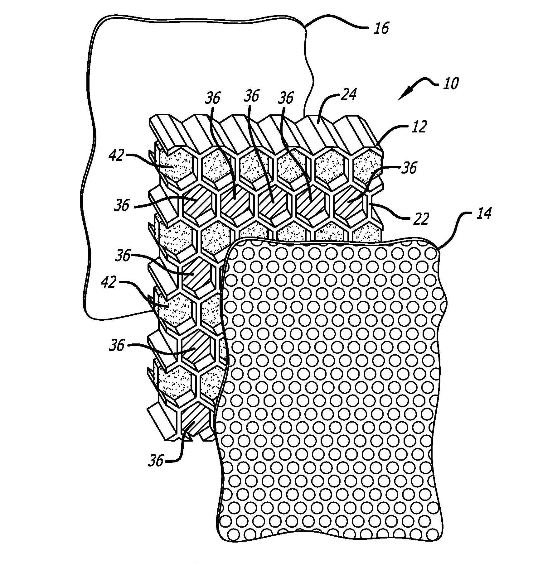
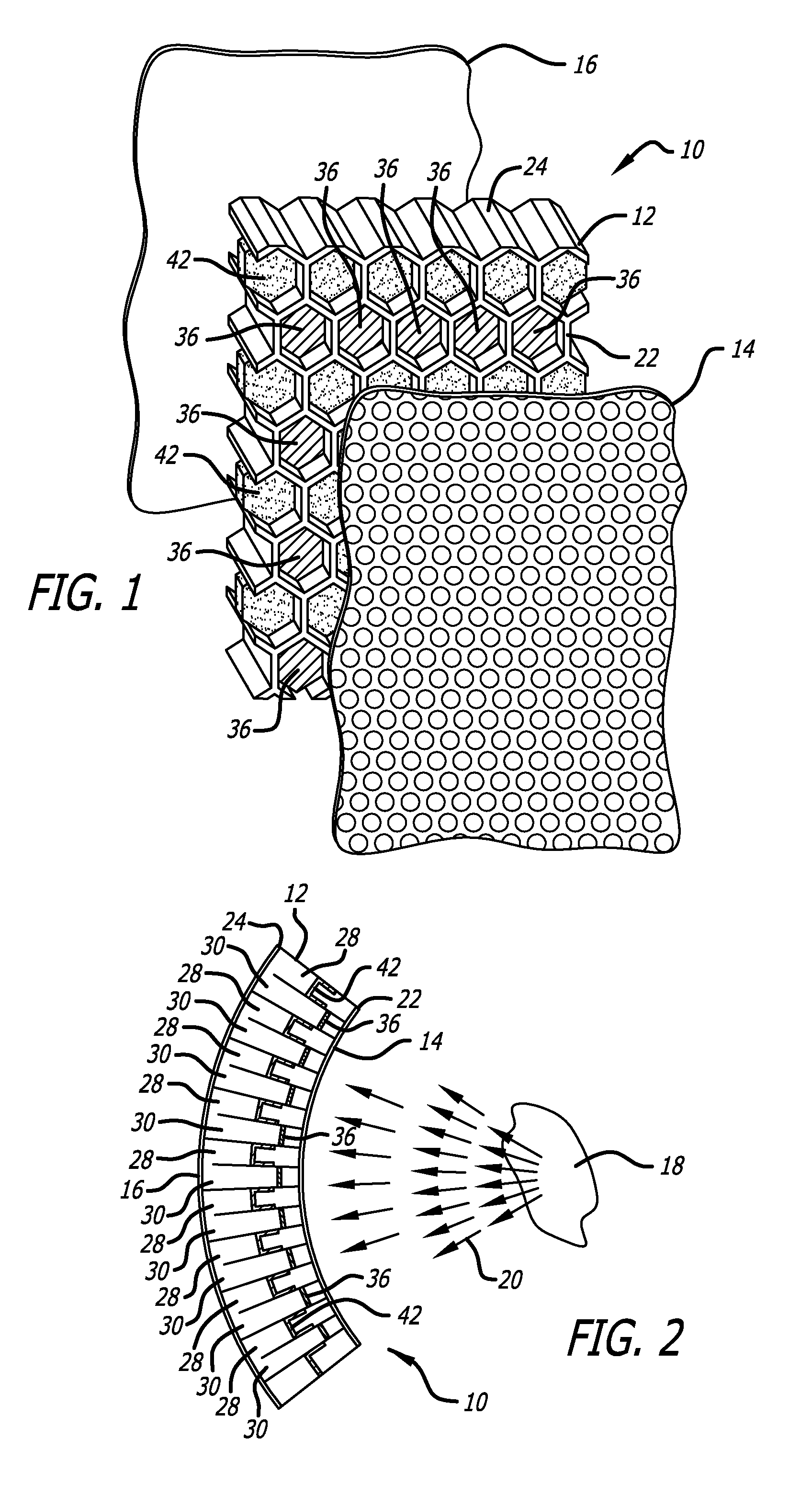
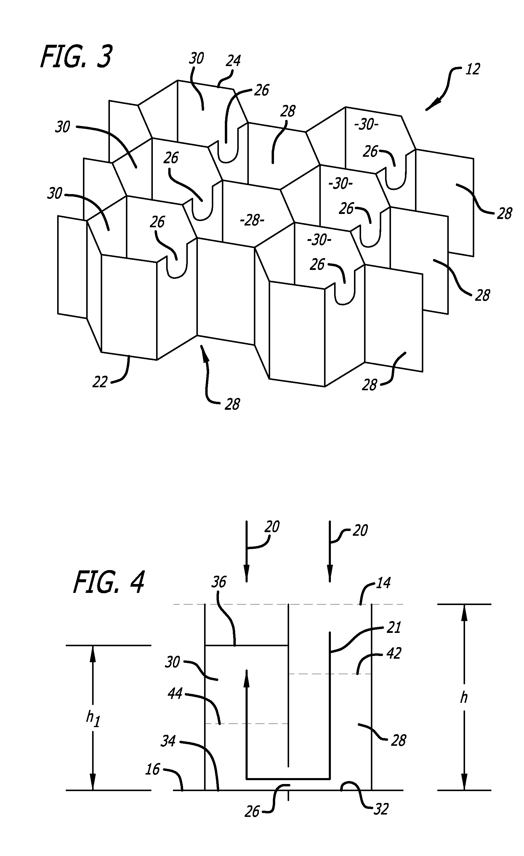
[0025]A partially exploded view of a portion of an exemplary acoustic structure 10 in accordance with the present invention is shown in FIG. 1. The acoustic structure 10 includes an acoustic honeycomb 12 which is sandwiched between a porous face sheet 14 and a solid acoustic barrier face sheet 16. The assembled acoustic structure 10 is shown in FIG. 2 where it is located adjacent to a noise source 18 which is generating noise as represented by arrows 20. Although the acoustic structure of the present invention may be used for dampening noise from a wide variety of noise sources, the acoustic structure is particularly well-suited for dampening noise generated by aircraft engines and particularly the large engines used for commercial aircraft. Accordingly, the acoustic structure shown at 10 in FIG. 2 is typically part of a nacelle which surrounds the central core of a turbofan jet engine 18.

[0026]As shown in the FIGS. 1-3, the honeycomb 12 includes a first edge 22 that is located clos...


PUM

PropertyMeasurementUnit
thicknessaaaaaaaaaa
temperaturesaaaaaaaaaa
areaaaaaaaaaaa

Abstract

The bandwidth or acoustical range of a nacelle or other type of acoustic structure is increased by acoustically coupling honeycomb cells together to form pairs of acoustic cells that have an effective acoustic or resonator length that is up to twice that of either acoustic cell taken alone.

Description

BACKGROUND OF THE INVENTION[0001]1. Field of the Invention[0002]The present invention relates generally to acoustic structures that are used to attenuate noise that emanates from a particular source. More particularly, the present invention is directed to providing relatively thin acoustic structures that are capable of attenuating a wide range of noise frequencies including relatively low-frequency noise, such as the low-frequency noise that is generated by the engines of aircraft.[0003]2. Description of Related Art[0004]It is widely recognized that the best way of dealing with excess noise generated by a specific source is to treat the noise at the source. This is typically accomplished by adding acoustic damping structures (acoustic treatments) to the structure of the noise source. One particularly problematic noise source is the jet engine used on most passenger aircraft. Acoustic treatments are typically incorporated in the engine inlet, nacelle and exhaust structures. These ac...

Claims


Application Information

Patent Timeline
Patent Type & Authority Applications(United States)
IPC IPC(8): E04B1/82B23P11/00
CPCG10K11/172Y10T29/49826Y10T29/4957B32B3/12B64D29/00
Inventor AYLE, EARL
Owner HEXCEL
Learn More