Vertical cavity surface emitting laser and image forming apparatus

Inactive Publication Date: 2012-05-03
CANON KK
View PDF2 Cites 3 Cited by
  • Summary
  • Abstract
  • Description
  • Claims
  • Application Information

AI Technical Summary

Benefits of technology

[0014]The present invention can realize a vertical cavity surface emitting laser capable of stable single longitudinal mode oscillation even if longitudinal multimode oscillation or longi

Problems solved by technology

This may not be satisfactory in attaining a st

Method used


Image

  • Vertical cavity surface emitting laser and image forming apparatus
  • Vertical cavity surface emitting laser and image forming apparatus
  • Vertical cavity surface emitting laser and image forming apparatus

Examples


first embodiment

[0045]An example of configuration of the vertical cavity surface emitting laser applying the present invention will be described as the first embodiment with reference to FIG. 4.

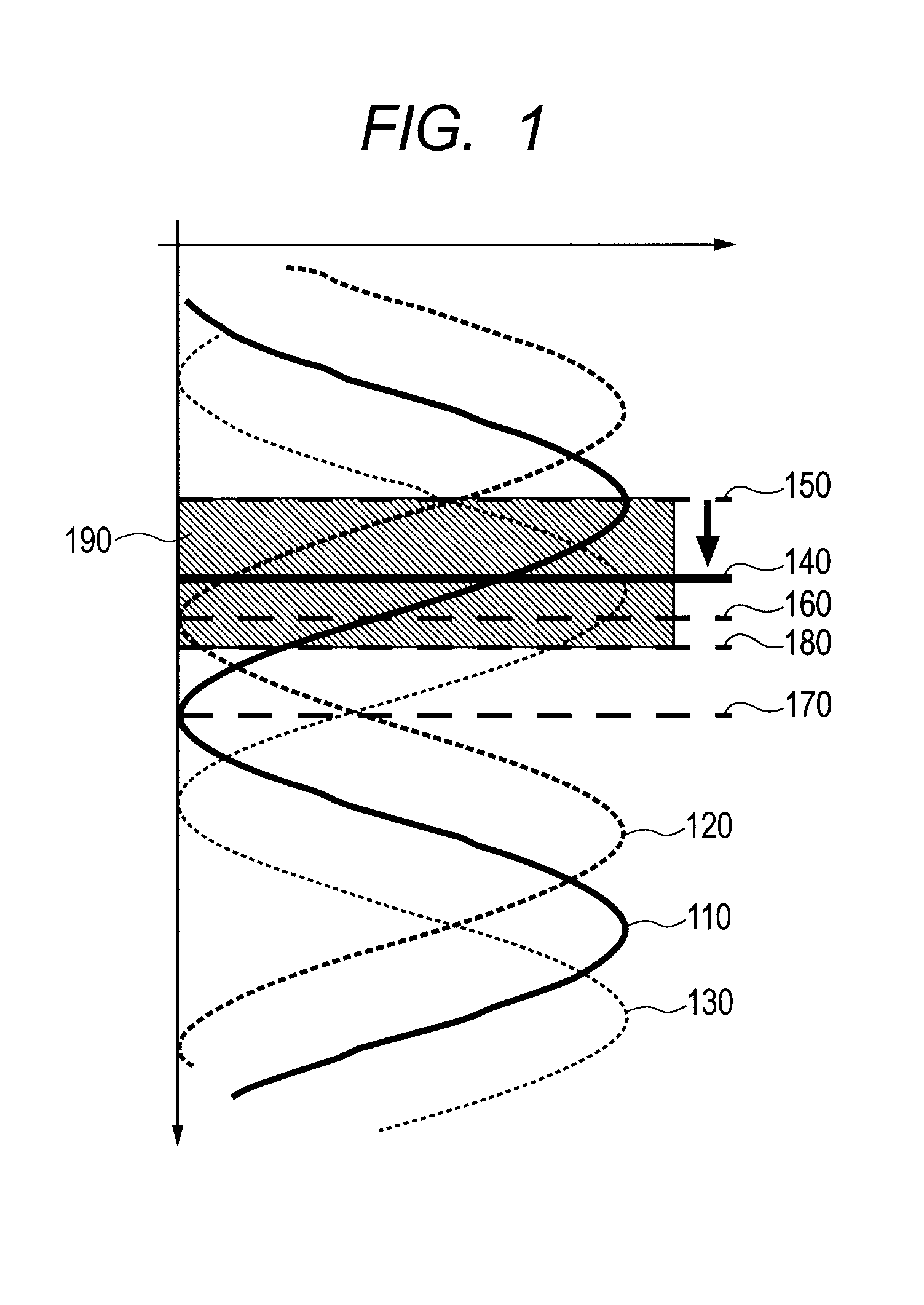
[0046]FIG. 4 illustrates a relationship between longitudinal modes and a gain spectrum of the vertical cavity surface emitting laser (hereinafter, “surface-emitting laser”) according to the present embodiment. The relationship between a resonant wavelength λ1 of a first longitudinal mode 410 and a resonant wavelength λ2 of a second longitudinal mode 420 is λ21. Although g3=0 in FIG. 4, it is only necessary to satisfy λ21, g1≠0, and g2≠0.

[0047]The active layer has a gain spectrum, in which the wave is generated at the wavelength λ1, and the difference between the wavelength λ1 and a peak wavelength λg of the gain spectrum determined by the active layer is an amount of detuning Δλ (=λ1−λg). The gain spectrum is expressed by a function g(y).

[0048]The present embodiment has a resonator structure in which the fir...

second embodiment

[0118]An infrared surface-emitting laser of wavelength 780 nm will be described as a second embodiment.

[0119]Unlike the first embodiment, λ2>λ1, g1≠0, g2≠0, and g3≠0 are satisfied in the configuration of the present embodiment.

[0120]Although a specific layer configuration from the lower multilayer reflecting mirror to the upper multilayer reflecting mirror of the present embodiment is different from that of the first embodiment, the fabrication method and the basic layer configuration of the surface-emitting laser are the same as in the first embodiment. Therefore, the description of the fabrication method, the substrate, and the electrode, for example, will not be repeated.

[0121]FIG. 7 illustrates a relationship between longitudinal modes and a gain spectrum of the surface-emitting laser according to the present embodiment. FIG. 7 illustrates a relationship diagram between gains g1, g2, and g3 and Δλ, ΔλN, and g(y) of an active layer related to a first longitudinal mode 710, a seco...

third embodiment

[0174]In a third embodiment, an example of applying a periodic gain structure using a plurality of active layers, instead of using one active layer as in the first area of the first embodiment, is described.

[0175]More specifically, a second active layer is placed in addition to the first active layer in the present embodiment. The first active layer and the second active layer are arranged in the first area.

[0176]FIG. 10 illustrates a cross-sectional schematic diagram for describing a layer configuration of a surface-emitting laser according to the present embodiment. In FIG. 10, the first area is formed by a lower clad layer 1040, a lower active layer 1050, an inter-active-layer spacer layer 1053, an upper active layer 1055, and an upper clad layer 1060. The upper active layer 1055 serves as the first active layer, and the lower active layer 1050 serves as the second active layer.

[0177]In the upper active layer 1055, as in the first embodiment, the gain is g1 and the confinement fa...


PUM


Abstract

Provided is a vertical cavity surface emitting laser that includes a plurality of laminated semiconductor layers including an active layer and that oscillates at a wavelength λ1, wherein a resonator is formed by upper and lower multilayer reflecting mirrors has a structure that generates a longitudinal multimode, and the first active layer is arranged at a position shifted from a standing wave loop of the first longitudinal mode. According to the vertical cavity surface emitting laser capable of suppressing oscillation of the second longitudinal mode with a large gain and capable of single longitudinal mode oscillation based on the first longitudinal mode, the longitudinal mode spacing is narrowed by increasing the length of the resonator for single transverse mode oscillation at a high output, and the single longitudinal mode oscillation is possible even if longitudinal multimode oscillation occurs.

Description

BACKGROUND OF THE INVENTION[0001]1. Field of the Invention[0002]The present invention relates to a vertical cavity surface emitting laser and an image forming apparatus using the vertical cavity surface emitting laser.[0003]2. Description of the Related Art[0004]A vertical cavity surface emitting laser (VCSEL) can extract light in a vertical direction relative to a semiconductor substrate. Therefore, a two-dimensional array can be easily formed with VCSELs.[0005]Various industrial applications of a surface-emitting laser array are expected, and for example, if a high-density two-dimensional laser array is used, applications to a high-speed high-definition electrophotographic system are possible. In an electrophotographic process, since stable and minute laser spots need to be formed on a photoconductor drum, a stable operation of a single transverse mode and a single longitudinal mode is necessary as a laser characteristic. By using the surface-emitting laser, a current confinement ...

Claims


Application Information

Patent Timeline
IPC IPC(8): H01S3/08
CPCB82Y20/00H01S5/0654H01S5/1221H01S5/18311H01S5/18358H01S5/34326
Inventor MATSUU, TOSHIMITSUUCHIDA, TAKESHI
Owner CANON KK
Why Eureka
Try Eureka