Ultrasonic motion sensor device

a motion sensor and ultrasonic technology, applied in the direction of electrical equipment, instruments, reradiation, etc., can solve the problem of unusable activation of corridor lighting, and achieve the effect of simple mounting

Inactive Publication Date: 2013-11-14
STEINEL
View PDF4 Cites 3 Cited by
  • Summary
  • Abstract
  • Description
  • Claims
  • Application Information

AI Technical Summary

Benefits of technology

[0004]The foregoing problem is solved by means of an ultrasonic motion sensor device of the present invention based on the idea of designing the ultrasonic sensor device for lighting control such that it has a comparatively directed emission and / or reception characteristic, in order therefore to generate a detection range which is elongated and narrow in relation thereto. This ensures that on the one hand, elongated areas, in particular corridors, can be monitored with a small number of such ultrasonic motion sensor devices, and on the other hand prevents ultrasonic waves being propagated into areas, in particular into adjacent rooms perpendicular to the main emission direction, thus preventing erroneous triggering of the lighting. According to the invention this is achieved by the fact that a horn (i.e. a funnel-shaped or trumpet-shaped outlet) is assigned to the at least one ultrasonic transducer, piezo-transducer or, more preferably, a quartz transducer, wherein according to the invention this horn does not directly adjoin the ultrasonic transducer, but is spaced apart from it by a resonant cavity (reflex chamber) to optimize the directional characteristics and filtering of the ultrasonic waves.
[0005]Furthermore, it is provided according to the invention that the maximum cross-sectional area of the preferred resonant cavity oriented perpendicular to the spacing direction between horn and ultrasonic transducer is greater than the cross-sectional area, preferably oriented parallel thereto, of a preferably circular impedance opening which the ultrasonic waves must pass through on their way between the ultrasonic transducer and the outer end of the horn, preferably implemented as a tractrix horn. The combination of horn and resonant cavity results in an efficient coupling of the ultrasonic transducer to the transmission medium, air, so that an optimal directivity / directional characteristic is obtained.
[0006]This further results in a high efficiency and hence a large range, since the above combination provides a focussing of the ultrasonic waves, resulting in a large range of the ultrasound while at the same time minimizing undesired propagation perpendicular to the main emission direction. The ultrasonic motion sensor device according to the invention is particularly suitable for use in long, narrow spaces, such as walkways and corridors and / or for the detection of temporarily present solid objects, for example, cars in parking spaces of car parks.
[0007]As mentioned above, the focussed and directed ultrasonic wave prevents it from being detected in adjacent areas, in particular rooms, parking spaces or the like, and therefore ensures a selective detection of objects or movements.
[0010]In order to obtain a maximally simple and easy-to-assemble motion detector, it is advantageous to extend the invention by providing the at least one ultrasonic transducer with an associated holder which is fixed onto a circuit board of the control device. It is especially advantageous if the holder is a plastic injection-moulded part, which is further preferably configured such that it can be clipped onto the printed circuit board.

Problems solved by technology

Known ultrasound motion alarms have the problem that the ultrasonic waves also propagate into other areas, for example through open doors into neighbouring rooms, so that movements are also detected there.
This is particularly problematic in elongated spaces, e.g. corridors, including school corridors, where as a result of the long length a plurality of ultrasonic sensors is required to cover the entire space and in addition, a plurality of doors normally opens into the elongated space, for example such that if one of the doors is open, movements in the adjoining rooms lead to an undesirable activation of the corridor lighting.

Method used


Image

  • Ultrasonic motion sensor device
  • Ultrasonic motion sensor device
  • Ultrasonic motion sensor device

Examples


Embodiment Construction

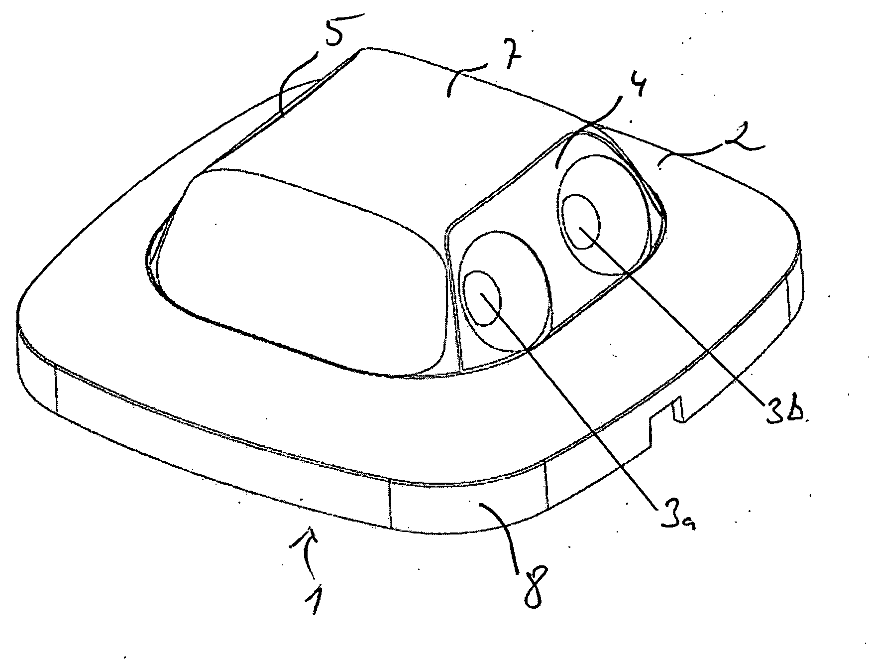
[0024]FIG. 1 illustrates a motion sensor device 1, shown rotated by 180° opposite to the direction of mounting on a ceiling. This comprises a housing 2 assembled from a plurality of plastic injection-moulded parts, in which housing a total of four horns are constructed, with only one pair of horns 3a, 3b being shown in the illustration.

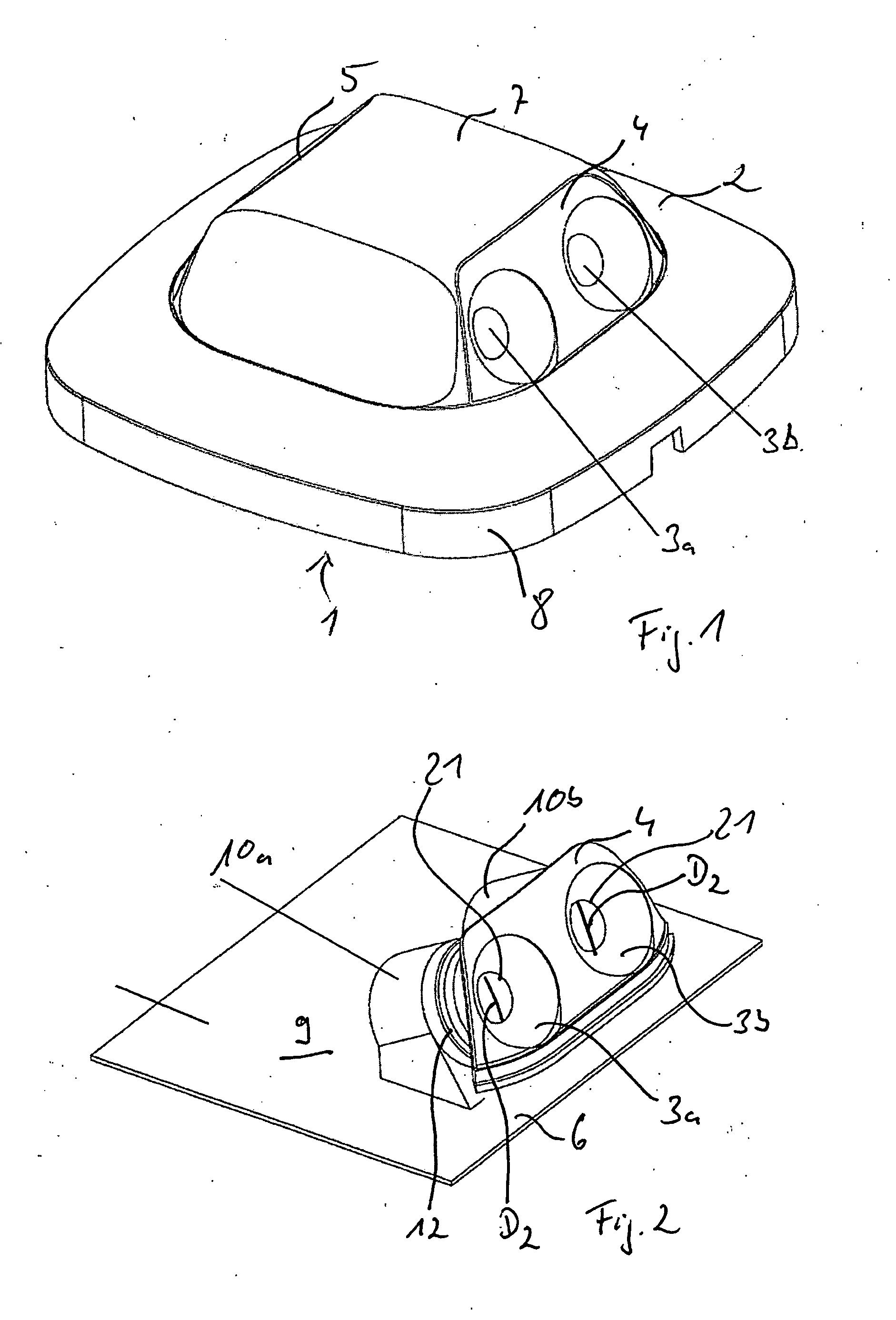
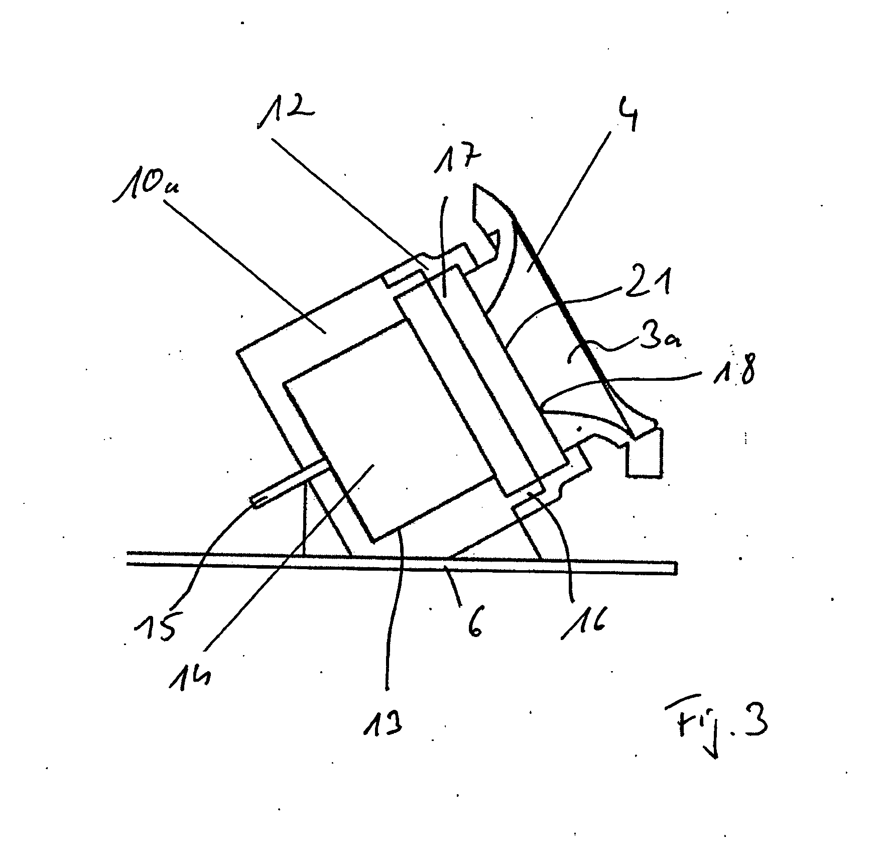
[0025]In the exemplary embodiment shown the housing 2 comprises two lateral housing shells 4, 5, arranged so that they face away from each other, which are implemented as plastic injection-moulded parts and which enclose an angle with a base surface of the device 1, and thus with a printed circuit board 6 shown in FIG. 2, such that in relation to a mounting position the horn pairs are directed downwards at an angle, wherein the horn pairs are arranged in different directions.

[0026]At the same time the housing shells 4, 5 form the horns, which are moulded into the former, wherein each housing shell 4, 5 forms one pair of horns 3a, 3b. The housing shell...


PUM


Abstract

An ultrasonic motion sensor device for lighting control, having a housing (10), preferably designed for ceiling-mounting, at least one ultrasonic transducer (11, 14) arranged in the housing (10) for sending and / or receiving ultrasonic waves through a housing opening associated with the ultrasonic transducer (11, 14), and having a control device (9) associated with the ultrasonic transducer (11, 14). The opening in the housing is formed by a horn which is spaced apart from the ultrasonic transducer (11, 14) via a resonator cavity arranged in the housing (2) and an impedance opening (21) is provided, preferably bounded by the horn, which the emitted and / or received ultrasonic waves (11, 14) are to pass through, the cross-sectional area (18) of which is less than a maximum cross-sectional area of the resonant cavity and than a maximum cross-sectional area of the horn.

Description

BACKGROUND OF THE INVENTION[0001]The invention relates to an ultrasonic motion sensor device, preferably designed for ceiling mounting, for controlling lighting, and to a lighting system.[0002]Ultrasonic sensor devices for lighting control in buildings are well known. These comprise pulsed ultrasonic transducers for emitting ultrasonic waves at a first pulse rate, and for receiving reflected ultrasonic waves at a second pulse rate. The ultrasonic transducer is associated with a control device, which on recognition of a frequency shift, detects a motion and activates or deactivates a lamp as a response thereto. Known ultrasound motion alarms have the problem that the ultrasonic waves also propagate into other areas, for example through open doors into neighbouring rooms, so that movements are also detected there. This is particularly problematic in elongated spaces, e.g. corridors, including school corridors, where as a result of the long length a plurality of ultrasonic sensors is r...

Claims


Application Information

Patent Timeline
Patent Type & Authority Applications(United States)
IPC IPC(8): H05B37/02G01S15/50
CPCH05B37/0227G01S15/50G01S7/521G01S15/523H04Q9/00H04Q2209/40H05B47/115Y02B20/40
Inventor MOELLER, THOMAS
Owner STEINEL
Why Eureka
Try Eureka