Method for fast spin-echo MRT imaging

a mrt imaging and fast technology, applied in the field of fast spinecho mrt imaging, can solve the problems of reducing the degree of effectiveness or efficiency of image recording, reducing the time loss of training data, and requiring correction of fold artifacts

Inactive Publication Date: 2013-11-14
MAX DELBRUECK CENT FUER MOLEKULARE MEDIZIN
View PDF4 Cites 11 Cited by
  • Summary
  • Abstract
  • Description
  • Claims
  • Application Information

AI Technical Summary

Benefits of technology

[0047]Phase coding in the sense of the invention is preferably a method for defining the lines of the measurement matrix. A magnetic field gradient is switched between the HF excitation pulse and reading out of the MR signal, for a short time, which gradient imposes a phase shift on the spins from line to line. For complete measurement of a slice, 256 or 512 phase coding steps, for example, have to occur, depending on the matrix. The subsequent Fourier-Transformation can assign the different phasing back to the corresponding lines.

Problems solved by technology

Folding artifacts that require correction result from subsampling.
These reduce the degree of effectiveness or the efficiency of image recording, and therefore can also benefit from any form of acceleration or improvement in the degree of effectiveness.
Time-nested recording of training data can, however, lead to greater time loss than recording of training data.

Method used


Image

  • Method for fast spin-echo MRT imaging
  • Method for fast spin-echo MRT imaging
  • Method for fast spin-echo MRT imaging

Examples


example 1

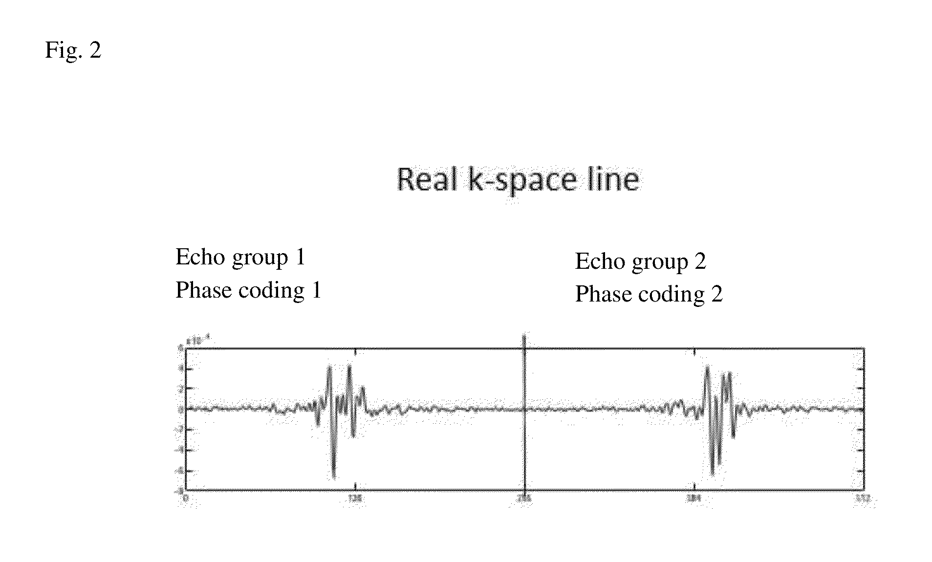
[0097]As exemplary embodiment, the autocalibrated split-echo approach (SCSE FSE) is listed in a preferred embodiment. In this connection, Echo 1 functions as the reference data set, with which the intensity profile of HF coil arrays can be determined. Echo group 2 functions as a subsampled data set. The data set from echo group 2 can be unfolded and reconstructed using the reference data from echo group 1.

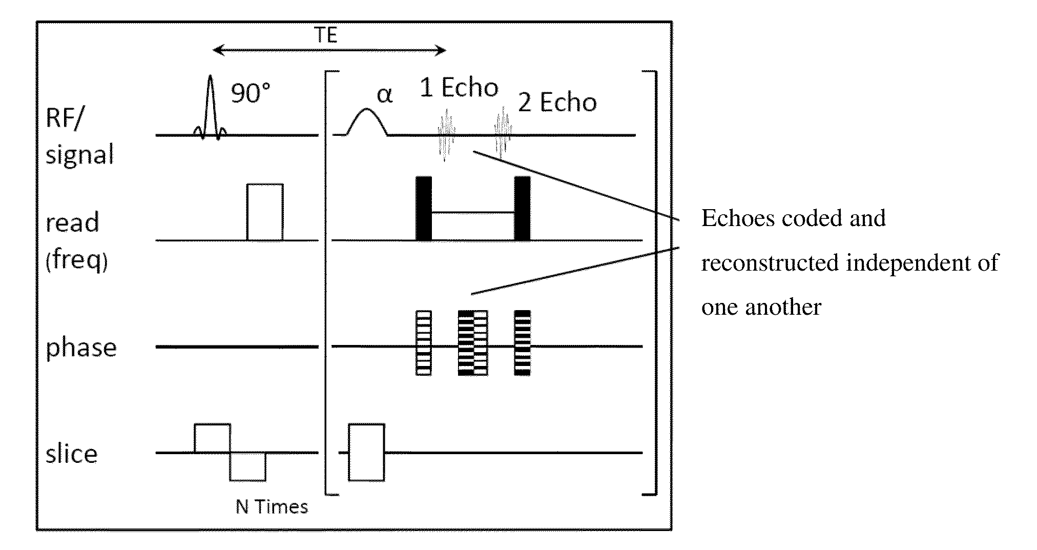
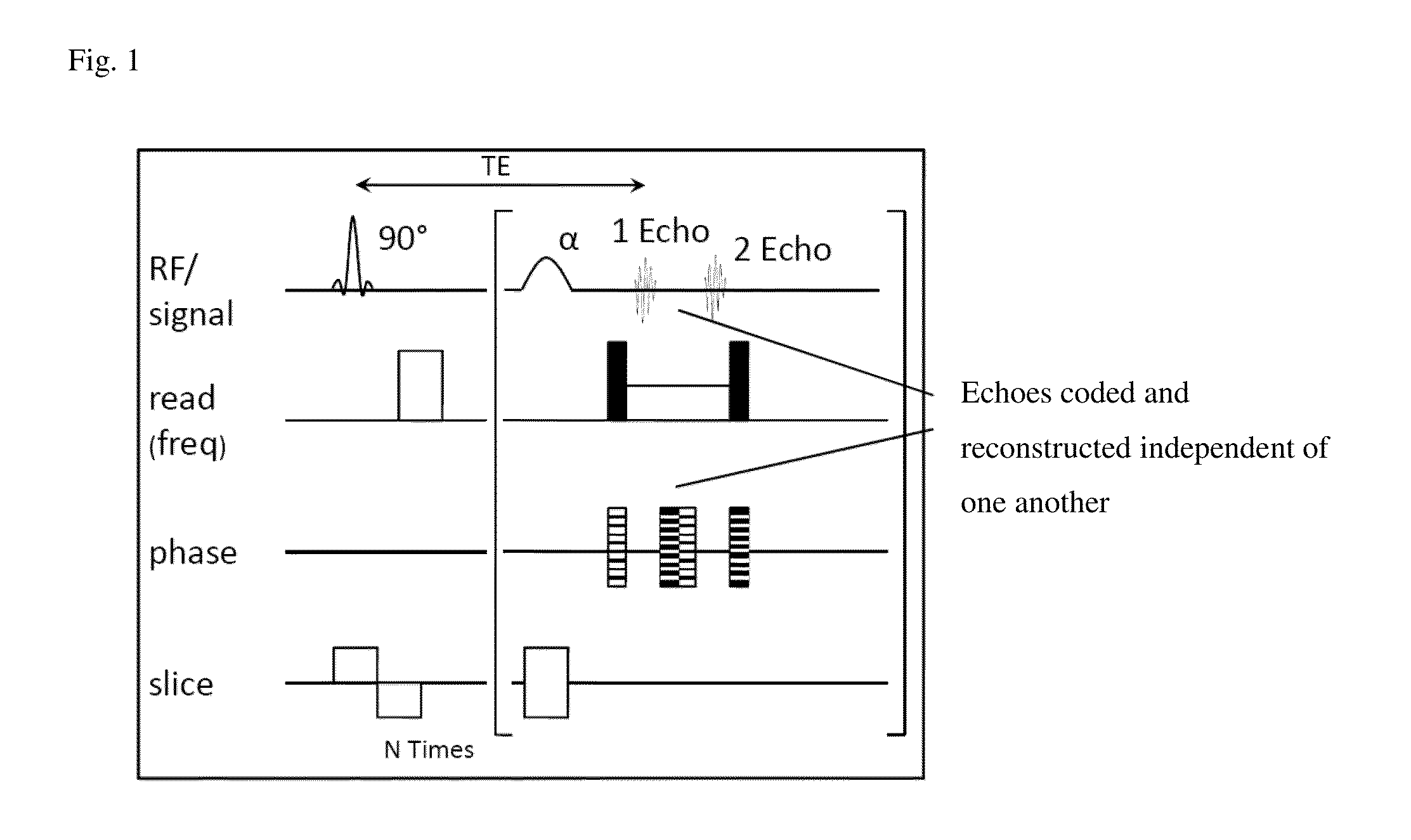
[0098]For implementation, independent gradients along the phase coding direction are generated, to separate even and odd echo groups and to code them independent of one another. One echo group serves for the reference map (see FIG. 3). Therefore an external reference scan becomes superfluous. The other echo group serves as the subsampled data set (see FIG. 4). This is unfolded using the reference map. FIG. 5 shows a completely reconstructed image.

[0099]The SCSE-FSE sequence was successfully implemented using acceleration factors of up to R=4. Higher acceleration factors can also be...

example 2

Heart Data Set for Autocalibrated Split-Echo Fast Spin-Echo Imaging

[0100]In the following, a split-echo is reconstructed using the example of the heart. In the reconstruction of the conventional SENSE algorithm, interference patterns that can be seen in the image occur as the result of the offset of the echoes in every k-space line. By means of processing of the raw data, it is possible to separate the echoes in the center of every k-space line. One data set serves as a reference map. The 32 individual coil images have a resolution of 270×256 pixels. The other data set serves for a reduced FOV. After the FOV data set was interpolated, both data sets pass through the algorithm (SENSE reconstruction). The resulting image has a resolution of 270×256 pixels. In this way, it was possible to reconstruct an image without folding artifacts.

[0101]For the SENSE reconstruction, the reference map is generated at the same time with the data set to be reconstructed. The two data sets contain dif...

example 3

[0102]An autocalibrated split-echo FSE technique with the following data was implemented:

[0103]Matrix size=512×526

[0104]Echo plus train length: 16

[0105]Number of dummy echoes: 8

[0106]in-plane resolution: (1.3×1.3) mm2

[0107]Slice thickness: 5 mm

[0108]TE: 67 ms

[0109]Repetition time (Time to Repetition=TR): 1 RR interval

[0110]Time between individual 180° refocusing pulses: 4.19 ms

[0111]Bandwidth±673 Hz / pixel

[0112]By means of additional gradients along the reading direction, even and odd echo groups were separated. The two echo groups were phase-coded differently. With one echo group, reference scans were drawn up, to generate a sensitivity map for the coils. This approach therefore requires no external reference scans and can therefore be referred to as autocalibrating. The second echo group was used to generate a subsampled data set. Acceleration factors from R=2 to R=4 were used. The SCSE-FSE imaging module was [word / words missing] with double IR (double inversion recovery) for supp...


PUM


Abstract

The invention relates to a method for fast autocalibrated spin-echo MRT imaging by means of independently coded echo groups, wherein one of the two echo groups is used for recording a reference data set or a training data set, while the other echo group is recorded in subsampled manner.

Description

CROSS REFERENCE TO RELATED APPLICATIONS [0001]This application claims priority to European application nos. EP 12162485.2, filed Mar. 30, 2012; EP 12162861.4, filed Apr. 2, 2012 and EP 12171685.6, filed Jun. 12, 2012, which are incorporated herein by reference in their entirety.FIELD OF THE INVENTION [0002]The invention is directed at a method for a fast, autocalibrated Spin-Echo Magnetic Resonance Tomography (MRT) technique by via independently coded and reconstructed echo groups.[0003]Magnetic resonance tomography is an imaging method. Cardiovascular magnetic resonance (MR) imaging requires fast imaging techniques to reduce movement artifacts and to shorten the examination time.BACKGROUND OF THE INVENTION [0004]Clinical MR imaging is based on the excitation of hydrogen protons. According to “Bohr's atom model” the proton of a hydrogen atom is positively charged and a negatively charged electron orbits around the proton.[0005]The proton of a hydrogen atom possesses an inherent rota...

Claims


Application Information

Patent Timeline
Patent Type & Authority Applications(United States)
IPC IPC(8): G01R33/565
CPCG01R33/5611G01R33/5676G01R33/56509G01R33/5617G01R33/5615
Inventor NIENDORF, THORALFHEZEL, FABIANKLIX, SABRINA
Owner MAX DELBRUECK CENT FUER MOLEKULARE MEDIZIN
Why Eureka
Try Eureka