Casing

a casing and shell technology, applied in the direction of machines/engines, stators, liquid fuel engines, etc., can solve the problems of increasing the weight of the engine, and increasing the risk of blade fragments passing through the casing to an unacceptable level, so as to improve the stiffness of the rib and the skin, reduce the possibility, and improve the effect of rib stiffness

Active Publication Date: 2013-11-14
ROLLS ROYCE PLC
View PDF10 Cites 18 Cited by
  • Summary
  • Abstract
  • Description
  • Claims
  • Application Information

AI Technical Summary

Benefits of technology

[0015]Each rib may have a wavy profile in a section taken through the ribs. Such an arrangement further improves the stiffness of the rib and the skin. The stiffness of the skin may be further increased by the provision of dimples thereto.
[0016]Each rib may have a hollow cavity open to the radially outer surface of the skin. The arrangement is advantageous as impact to the rib causes spreading of the load and reduces the possibility of the rib being pushed through the outer casing.

Problems solved by technology

Unfortunately, the use of materials similar to that of the blades is expensive due to the price of the material.
Other materials which offer the same or greater hardness are typically much heavier and the significant use of these would increase the weight of the engine to an unacceptable level.
The use of this material for the containment case increases the risk of blade fragments passing through the casing to an unacceptable level.

Method used


Image

  • Casing
  • Casing
  • Casing

Examples


Embodiment Construction

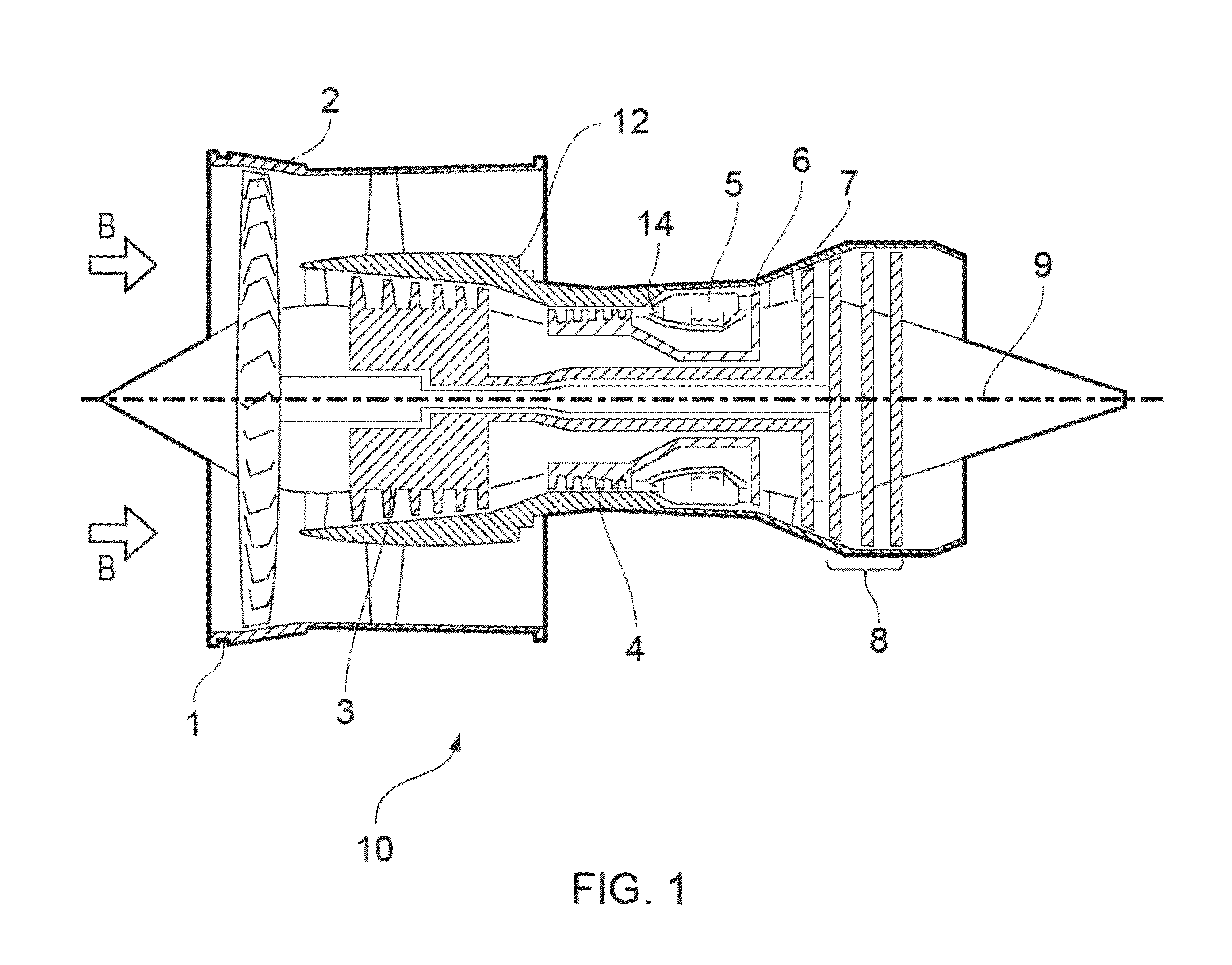
[0025]With reference to FIG. 1, a ducted fan gas turbine engine generally indicated at 10 comprises, in axial flow series, an air intake 1, a propulsive fan 2, an intermediate pressure compressor 3, a high pressure compressor 4, combustion equipment 5, a high pressure turbine 6, an intermediate pressure turbine 7, a low pressure turbine 8 and an exhaust nozzle 9.

[0026]Air entering the air intake 1 is accelerated by the fan 2 to produce two air flows, a first air flow into the intermediate pressure compressor 3 and a second air flow that passes over the outer surface of the engine casing 12 and which provides propulsive thrust. The intermediate pressure compressor 3 compresses the air flow directed into it before delivering the air to the high pressure compressor 4 where further compression takes place.

[0027]Compressed air exhausted from the high pressure compressor 4 is directed into the combustion equipment 5, where it is mixed with fuel that is injected from a fuel injector 14 and...


PUM

PropertyMeasurementUnit
stagger angleaaaaaaaaaa
diameteraaaaaaaaaa
skin thicknessaaaaaaaaaa

Abstract

A containment case for a gas turbine including: a cylindrical outer casing extending about an axis and having a radially outer and a radially inner surface; a coaxially arranged cylindrical inner skin formed of a harder material than the outer casing joined to the inner surface of the cylindrical outer casing; and an array of ribs extending radially from the inner skin towards the axis. The case for can have the coaxially arranged cylindrical inner skin formed of a harder material than the outer casing joined to the inner surface of the cylindrical outer casing by a galvanic isolation layer.

Description

TECHNICAL FIELD OF INVENTION[0001]The present invention relates to turbine engines and in particular cases surrounding rotatable or rotating parts and particularly containment cases for a fan of a gas turbine.BACKGROUND OF INVENTION[0002]Rotating components in a gas turbine engine can, in rare situations, become released from their mounts. Containment systems are provided in a gas turbine engine to capture these released components and dissipate a significant proportion of the energy of the component.[0003]The fan cases in particular, owing to the length of the fan blades, is one of the largest components on the engine—the fan case of the Trent XWB has a diameter of around 3 metres. Because of its size the fan case is often one of the heaviest components of the engine.[0004]Fan cases have, in the past, had a rigid outer skin within which a low density liner is positioned and which can crush during impact of a released blade to absorb some of the energy. The outer skin is typically o...

Claims


Application Information

Patent Timeline
Patent Type & Authority Applications(United States)
IPC IPC(8): F01D25/24
CPCF01D25/24F05D2300/171F01D21/045F05D2300/121F05D2300/173F05D2300/603F05C2201/021F05C2201/046F05C2201/903F05C2253/04F05D2300/21
Inventor FINLAYSON, JAMES ALEX
Owner ROLLS ROYCE PLC
Why Eureka
Try Eureka