
Duct architecture for regulating climate zone in a vehicle

a technology of duct system and climate zone, which is applied in the direction of vehicle components, air-flow control members, vehicle heating/cooling devices, etc., can solve the problems that the current design of vehicle air ducts cannot be regulated, and achieve the effects of reducing the total volume of air provided to the duct, reducing the electrical consumption of the hvac blower, and less cooling or heating

Inactive Publication Date: 2013-11-14
FORD GLOBAL TECH LLC
View PDF39 Cites 0 Cited by
  • Summary
  • Abstract
  • Description
  • Claims
  • Application Information

AI Technical Summary

Benefits of technology

[0005]By allowing the selective flow of air through the airflow channels the total volume of air being provided to the duct may be reduced, thus reducing the electrical consumption by the HVAC blower. Similarly the reduced airflow requires less cooling or heating and thus also reduced power required by the HVAC compressor or powered heat sources (such as a PTC [positive temperature coefficient] heater). The arrangement of the present invention thus provides for controlled and optimum airflow throughout the interior of the vehicle with minimum energy requirements.

Problems solved by technology

Other than selective closure of the panel registers current designs of vehicle air ducts cannot be regulated.
This situation where the control of air flow is inflexible creates a variety of difficulties in that key vehicle occupants sit in different vehicle positions (in the driver seat or in the rear seat) in different markets worldwide.

Method used


Image

  • Duct architecture for regulating climate zone in a vehicle
  • Duct architecture for regulating climate zone in a vehicle
  • Duct architecture for regulating climate zone in a vehicle

Examples


Embodiment Construction

[0013]In the following figures, the same reference numerals are used to refer to the same components. In the following description, various operating parameters and components are described for one constructed embodiment. These specific parameters and components are included as examples and are not meant to be limiting.

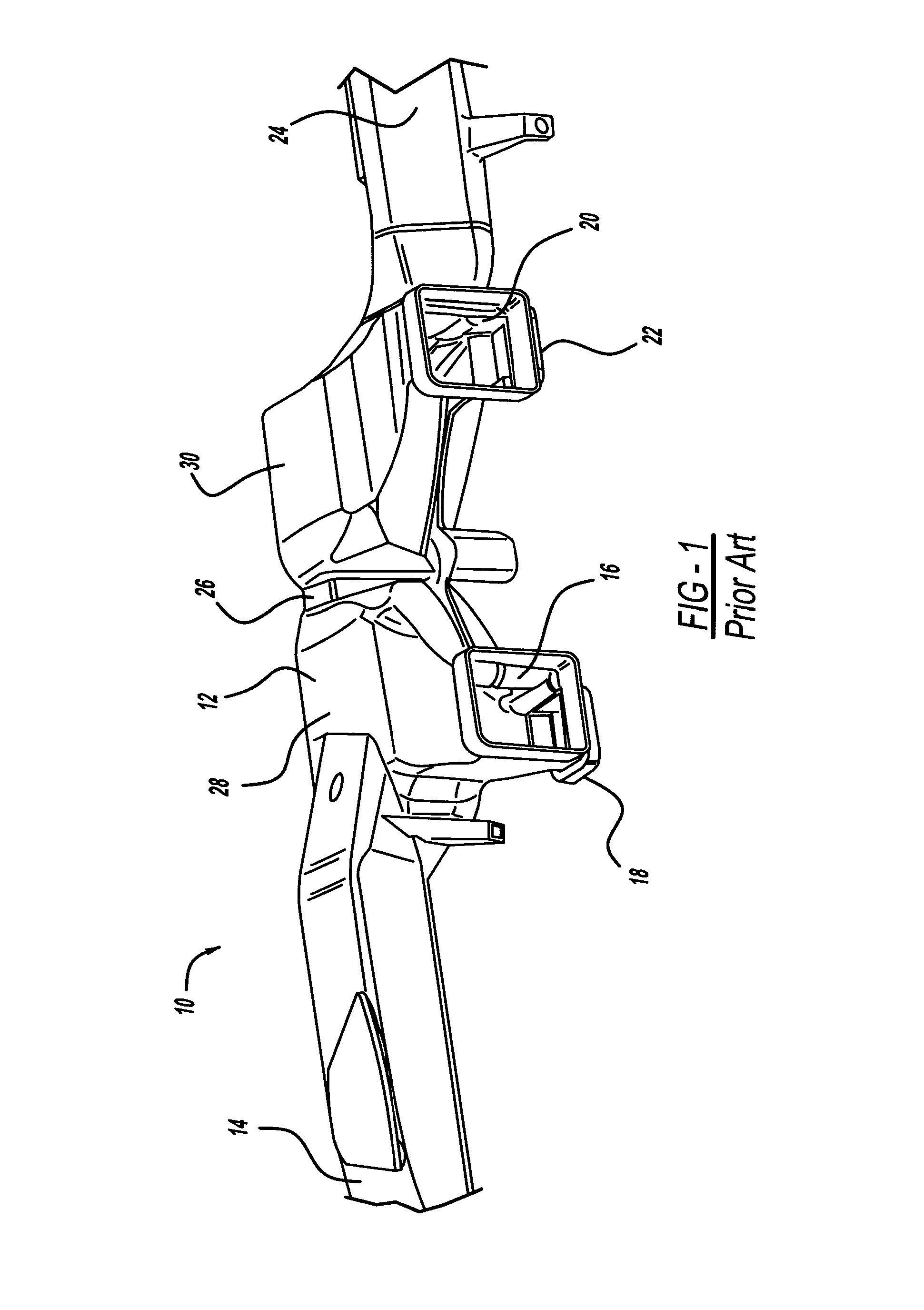
[0014]With reference to FIG. 1, a perspective view is shown of an airflow distribution duct according to the known art, generally illustrated as 10. The airflow distribution duct 10 includes a body 12, a first outlet 14, a second outlet 16, a third outlet 18, a fourth outlet 20, a fifth outlet 22, and a sixth outlet 24. There can be a greater or lesser number of outlets as is known in the art and the arrangement shown is only for illustrative purposes as representing the state of the prior art. Of particular interest is the body 12 which conventionally includes a plenum section for receiving inflowing air coming from the HVAC to which individual outlets 14, 16, 18, 20...


PUM


Abstract

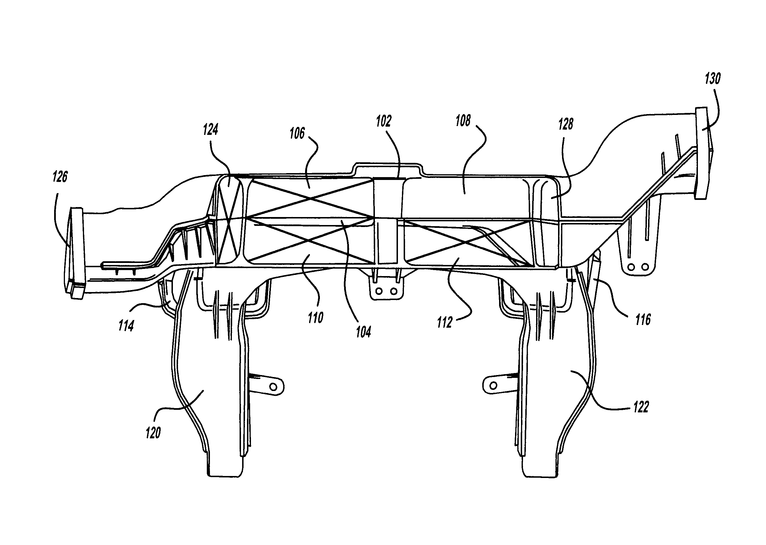
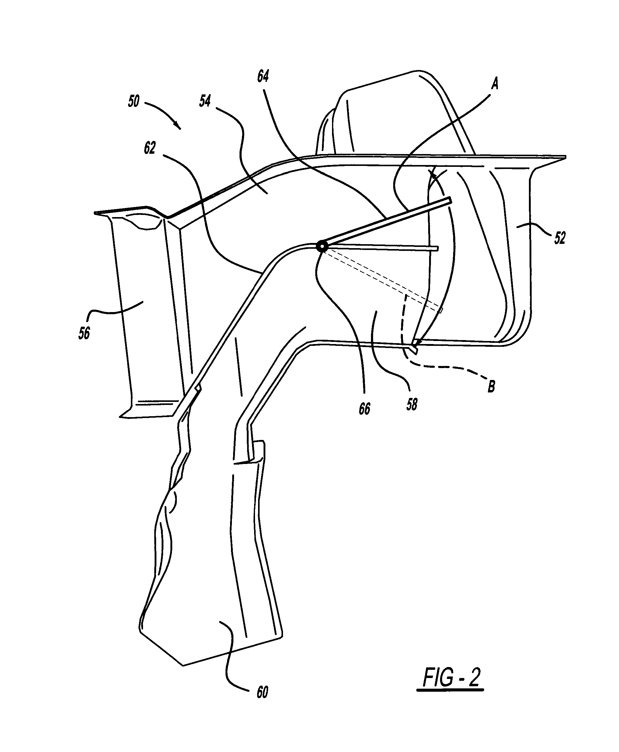
A climate control duct architecture having articulated and controlled interior surfaces to deliver variable and controllable airflow to target zones in the vehicle upon demand. By creating zone climates within the vehicle and providing conditioned airflow to only desired vehicle seating positions, the volume of necessary airflow is minimized, the need for cooling is reduced, and flexibility of the system is created. The interior surface may be mechanically or electrically controlled and may be situated in the common central “octopus” duct.

Description

TECHNICAL FIELD[0001]The present invention relates generally to climate control duct systems for vehicles. More particularly, the present invention relates to a climate control duct architecture having articulated and controlled interior surfaces to deliver variable and controllable airflow to occupants in target zones in the vehicle upon demand. By strategic regulation of the airflow the heating and cooling of different zones can be adjusted to meet the specific needs of vehicle occupants as well as optimize HVAC performance while minimizing energy usage.BACKGROUND OF THE INVENTION[0002]Modern vehicle interiors are provided with climate control systems. Central to the climate control system is the HVAC which produces climatized air for distribution into the interior of the vehicle through a variety of ducts. Known arrangements of ducts in climate control systems include a path to the panel registers and to the console which takes place at a distance away from the air outlet of the ...

Claims


Application Information

Patent Timeline
Patent Type & Authority Applications(United States)
IPC IPC(8): B60H1/26
CPCB60H1/26B60H1/00564F24F13/10
Inventor KUMAR, MUKESHHOKE, PAUL BRYAN
Owner FORD GLOBAL TECH LLC
Learn More