
Image processor and method therefor

a technology of image processor and processor, applied in the field of image processor and method therefor, can solve the problems of heavy load of processor, slow movement of some areas of the screen, and very fast movement of some areas

Inactive Publication Date: 2013-11-14
EPX LP
View PDF5 Cites 1 Cited by
  • Summary
  • Abstract
  • Description
  • Claims
  • Application Information

AI Technical Summary

Benefits of technology

The purpose of the patent is to provide a way to reduce the workload when showing images of fast movement only in a part of the screen. The technical effect of this invention is to make image processing faster and more efficient.

Problems solved by technology

When performing rendering processing, there is a case in which a movement of some area in the screen is very fast, and that of the other area is slow.
However, in the image processor of prior art, there is a problem that it is required that rendering processing of high flame late is performed with respect to area in which movement is slow in order to meet a condition of image quality of area in which movement is fast, therefore a load of the processor is heavy.

Method used


Image

  • Image processor and method therefor
  • Image processor and method therefor
  • Image processor and method therefor

Examples


Embodiment Construction

[0051]Below a slot machine of a pachinko parlor of an embodiment of the present invention will be explained.

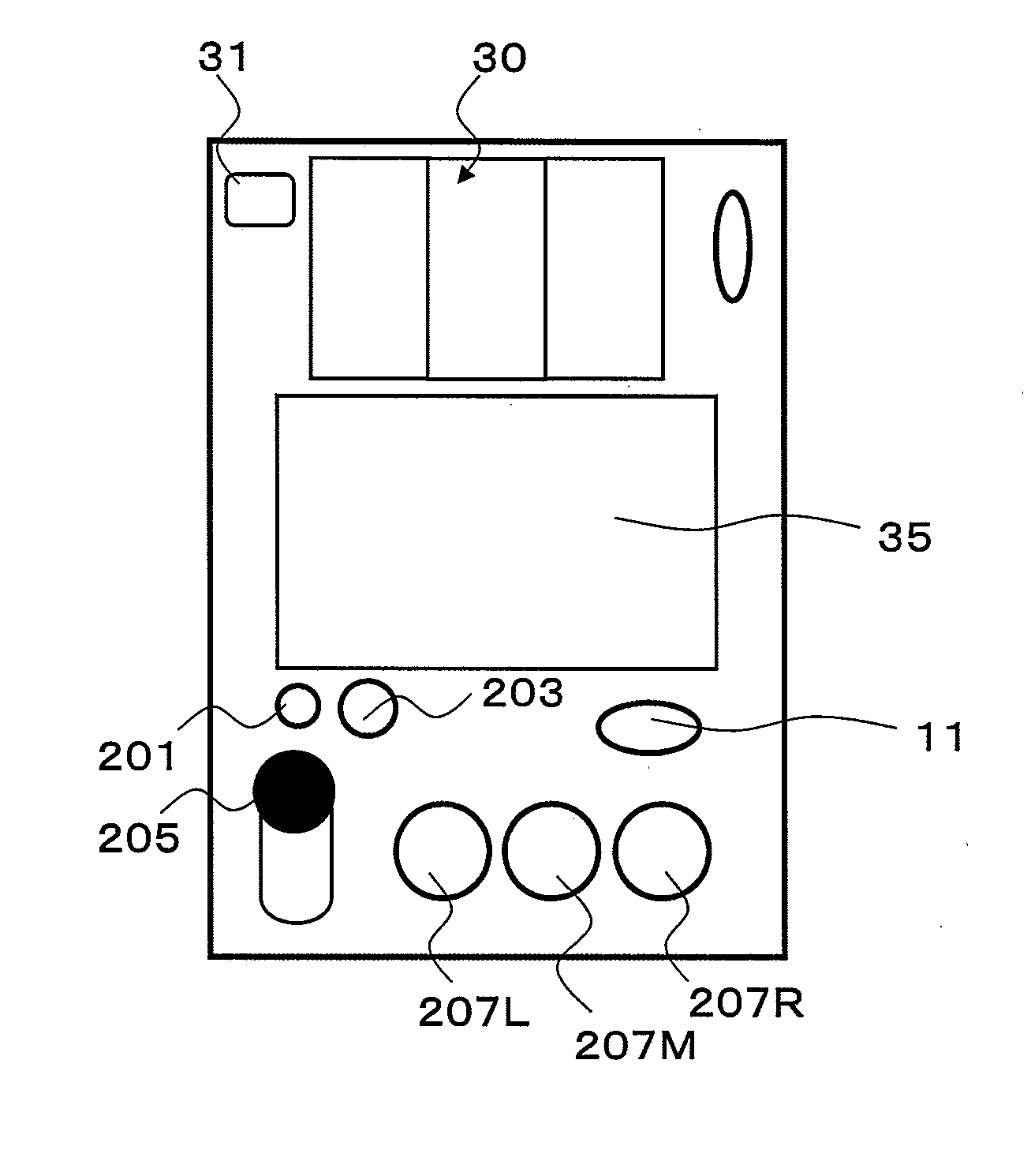
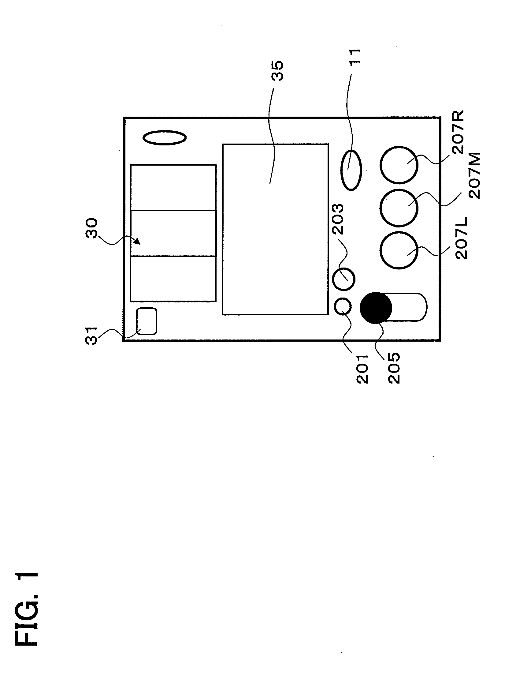
[0052]FIG. 1 is a drawing for explaining a display and an operation unit, etc. located at front of the slot machine of the present invention.

[0053]As shown in FIG. 1, a main-reel unit 30, notice lamp 31, display 35, medal insert unit 11, one piece bet button 201, three pieces bet button 203, start lever 205, left stop button 207L, middle stop button 207M and right stop button 207R are located in front of the slot machine 1.

[0054]The main-reel unit 30 is an example of the display of the present invention.

[0055]The start lever 205 is an example of the start instruction input unit of the present invention.

[0056]The left stop button 207L, middle stop button 207M and right stop button 207R are an example of the end instruction input unit of the present invention.

[0057]The main-reel unit 30 has three reels (main-reels) which several kinds of symbols are formed on peripheral surface ...


PUM


Abstract

By rendering lower half of 30 FPS in the processing of even numbered frame of 60 fps and rendering upper half of 30 fps in the processing of odd numbered frame, the processing load of the processor 70 can be reduced to half. Thus, by delaying image rendering, the image quality degradation can be prevented, therefore stable high-quality images can be displayed.

Description

FIELD OF INVENTION[0001]The present invention relates to an image processor and method therefor.BACKGROUND[0002]When performing rendering processing, there is a case in which a movement of some area in the screen is very fast, and that of the other area is slow.Problem to be Solved[0003]However, in the image processor of prior art, there is a problem that it is required that rendering processing of high flame late is performed with respect to area in which movement is slow in order to meet a condition of image quality of area in which movement is fast, therefore a load of the processor is heavy.[0004]The present invention was made in view of these situations, the purpose of the present invention is to provide an image processor and method therefor which can reduce load of processing when displaying image of fast movement only in a part of area of screen.SUMMARY OF INVENTIONS[0005]The present invention is an image processor comprising: a first memory group comprising a first memory a...

Claims


Application Information

Patent Timeline
Patent Type & Authority Applications(United States)
IPC IPC(8): G07F17/32G07F17/34
CPCG07F17/3211G07F17/34G06T13/00G06T15/005A63F5/04A63F13/00
Inventor KUMAGAI, HIROSHIMIYAZAKI, TAKAYUKI
Owner EPX LP
Learn More