Cable anchor systems and methods

a cable anchor and system technology, applied in the field of cable anchor systems and methods, can solve the problems of cable not being properly stabilized in the bone fracture, bone screw may only penetrate the cortex region of the bone,

Inactive Publication Date: 2013-11-14
TRAUNER KENNETH B
View PDF3 Cites 9 Cited by
  • Summary
  • Abstract
  • Description
  • Claims
  • Application Information

AI Technical Summary

Benefits of technology

[0023]Currently cable systems are used almost exclusively for circular constructs with the cable passed around the bone circumferentially and secured to itself. The inventive cable system utilizes bone coupling devices to keep the cables in place on the bone. By coupling the cable anchors and cable crimps to the bone, cable systems to be designed with the cables extending across portions of th

Problems solved by technology

However if a tack type of screw is selected, then the bone screw may only penetrate the cortex region of the bone.

Method used


Image

  • Cable anchor systems and methods
  • Cable anchor systems and methods
  • Cable anchor systems and methods

Examples


Embodiment Construction

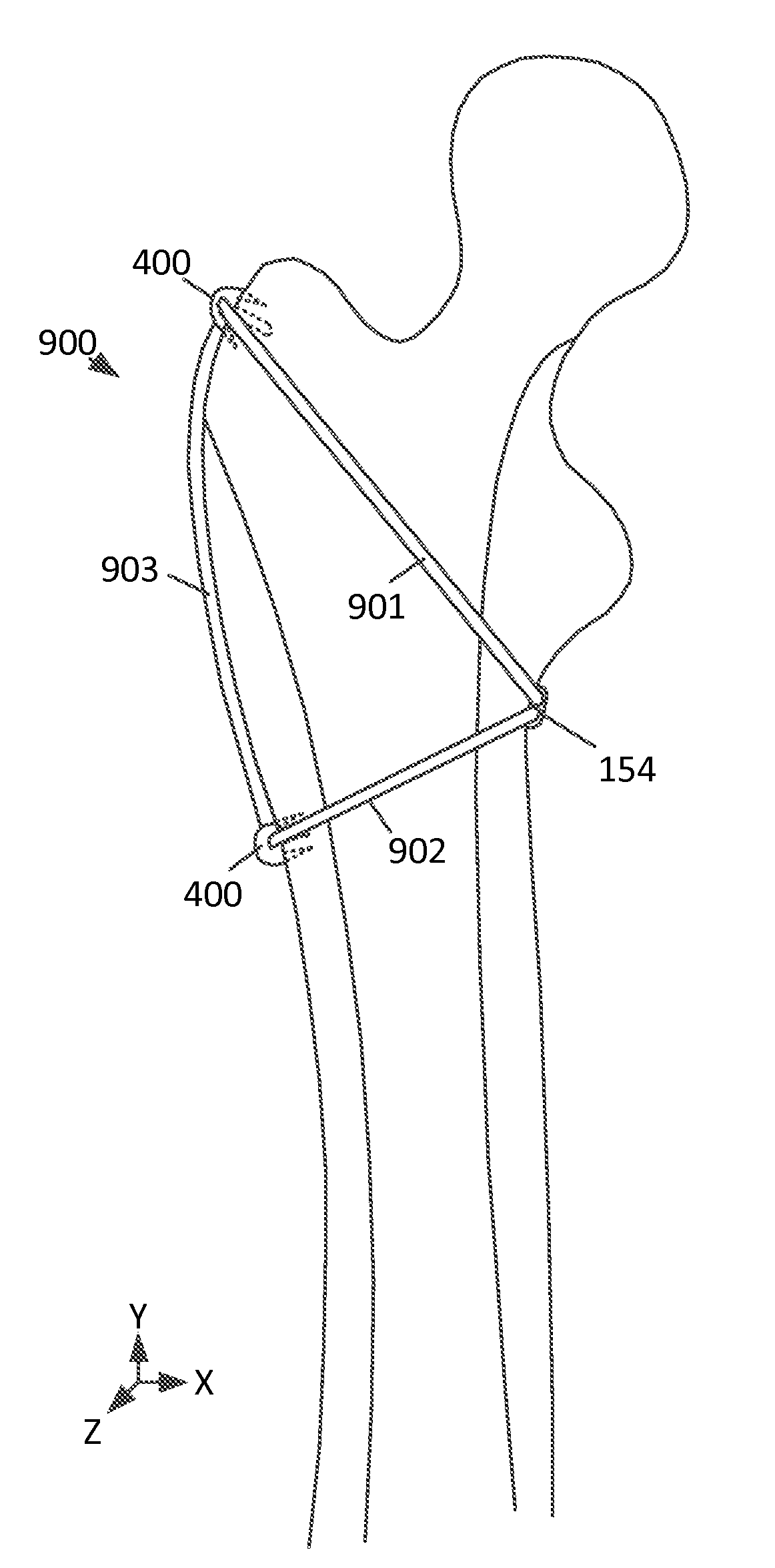
[0056]The inventive cable anchor system can include: a cable, a cable crimp and the cable anchor. The cable can be made of many strands of metal wire that are laid or twisted into a helix manner. Because the cable consists of many thin diameter pieces of wire, the cable is flexible and can bend in smaller radius than a solid metal rod.

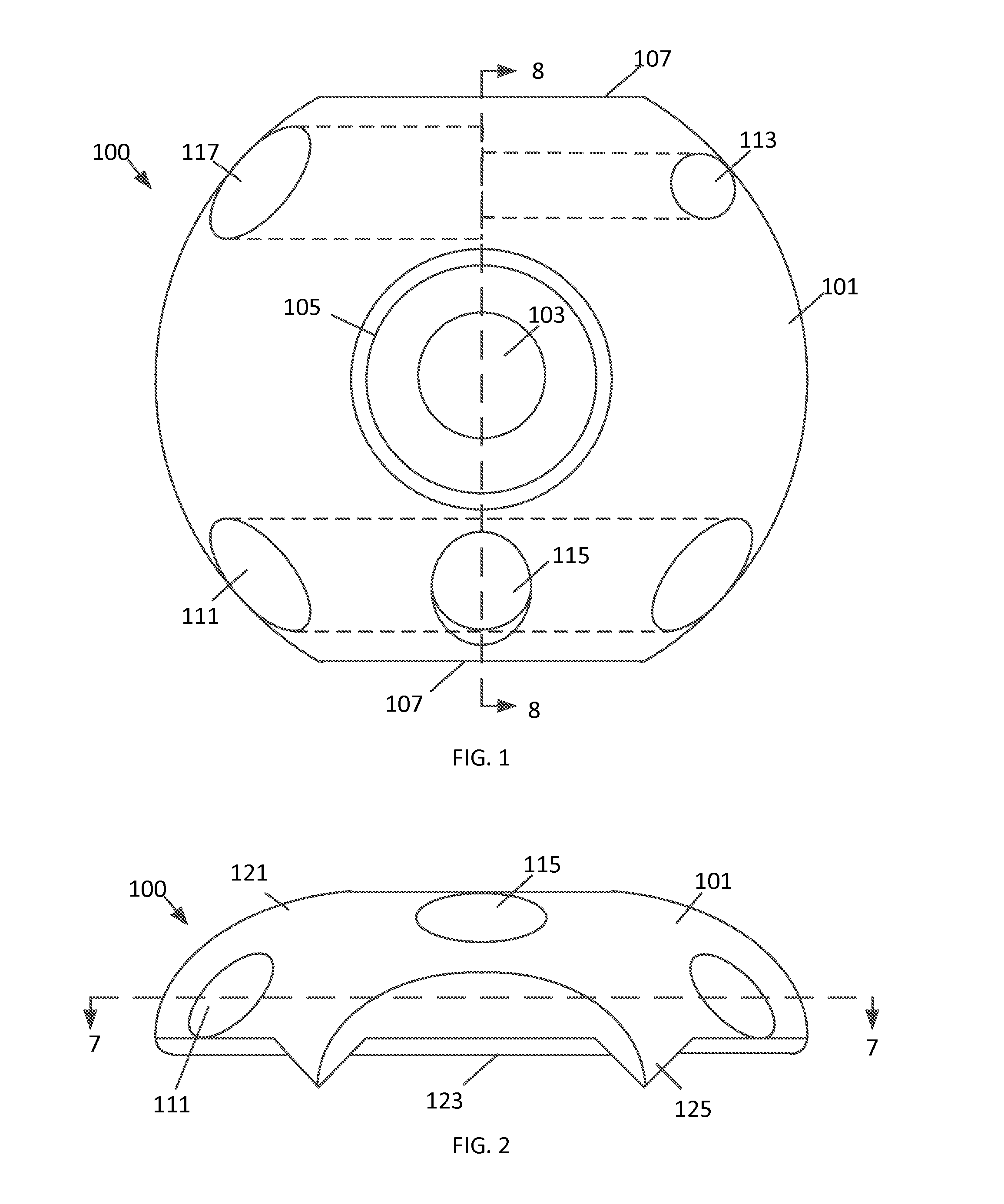
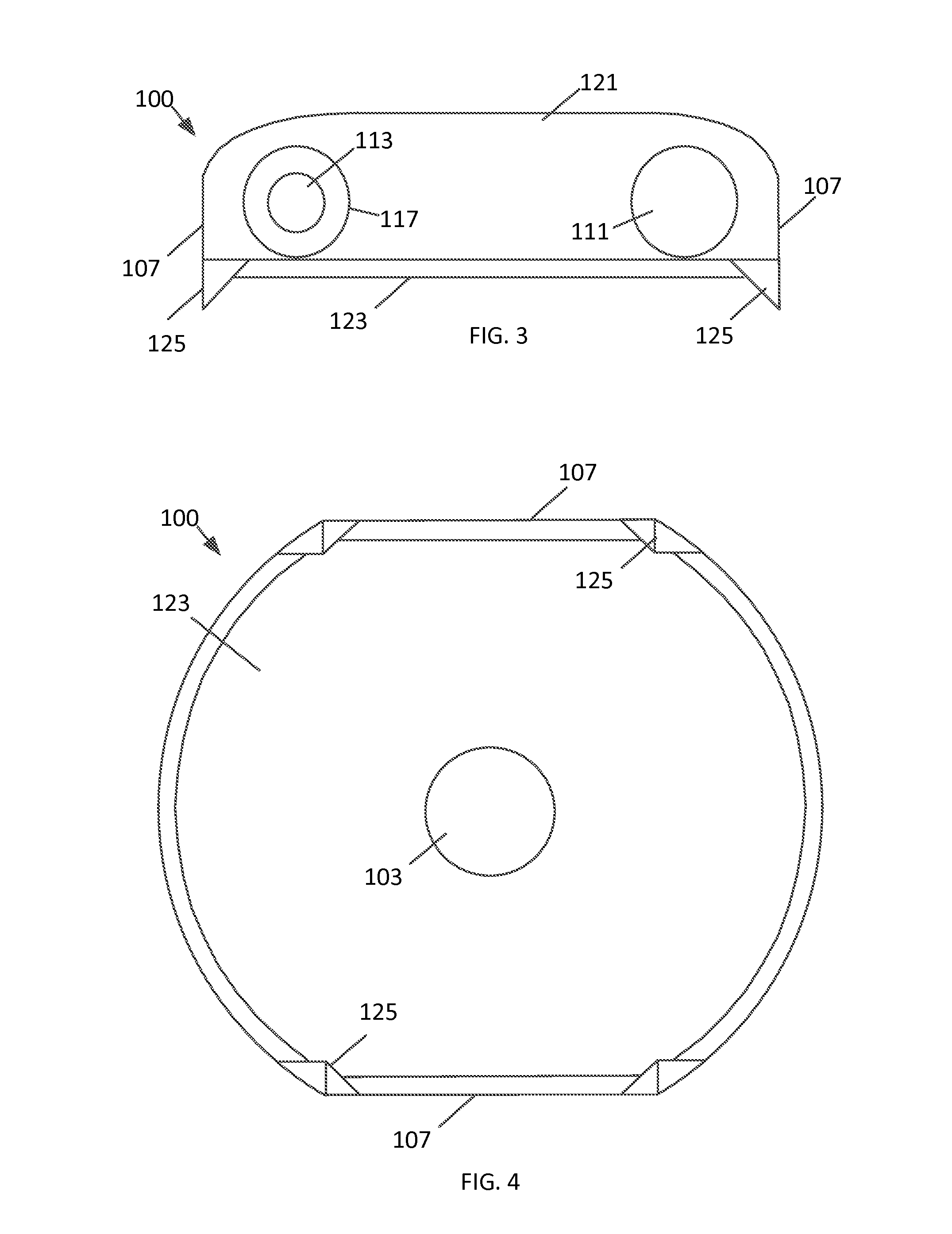
[0057]With reference to FIGS. 1-4 different views of an embodiment of a cable crimp 101 are illustrated. FIG. 1 illustrates a top view of the cable crimp 101. In this embodiment, the cable crimp 100 has a circular body 101 having a center hole that extends through the center of the body 101. The upper portion of the center hole 105 can have a wider diameter than the lower portion of the center hole 103. The body 101 can have flat sections 107 on opposite sides of the body 101 that can be used to grip and rotate the body 101. The body 101 can also have a first cable hole 111 and a second cable hole 113 that extend horizontally through the body 101. The ...


PUM


Abstract

The cable system includes a cable, cable anchors and/or cable crimps. The cable anchors and cable crimps have mounting holes that are used to secure the cable anchors and cable crimps to bones of patients with bone screws. Once the cable anchors and/or cable crimps are attached to the bone, the cable wrapped around the bone and placed through the cable anchors and cable crimps. The cable is tensioned and a locking mechanism is used to lock the cable crimp to the cable. The cable anchors and cable crimps prevent the cable from moving on the bone.

Description

CROSS REFERENCE TO RELATED APPLICATIONS[0001]This application claims priority to U.S. Provisional Application No. 61 / 646,675, Systems And Methods For Providing Cable Anchor Systems, filed May 14, 2012 which is hereby incorporated by reference in its entirety.BACKGROUND[0002]Cable systems are used to stabilize fractures of bones. Cables can be made of stainless steel pliable cords that are wrapped circumferentially around bone(s). A first end of the cable is free on first end and a second end of the cable is attached to a cable crimp. To use the cable system, the cable crimp which is placed against the bone and the first free end of the cable is wrapped around the bone and coupled to the cable crimp. A separate cable tensioner instrument is then slid over the free end of the cable until the tip of the tensioner is up against the exit hole of the cable crimp. The surgeon uses the tensioner to apply tension to the cable. Once the desired tension is applied, the cable is crimped to the ...

Claims


Application Information

Patent Timeline
IPC IPC(8): A61B17/82
CPCA61B17/82
Inventor TRAUNER, KENNETH B.
Owner TRAUNER KENNETH B
Why Eureka
Try Eureka