
Implant for fixation of first and second bones and method of fixing first and second bones using the implant

Active Publication Date: 2013-11-14
TRIMED
View PDF16 Cites 21 Cited by
  • Summary
  • Abstract
  • Description
  • Claims
  • Application Information

AI Technical Summary

Benefits of technology

The invention is an implant for fixation of bones at a specific site. The implant has a body with a central axis and a depth dimension between first and second ends. The body has an outer surface that matches a tapered surface around a receptacle formed at the site by rotating a cutting element. The body is designed to fit snugly into the receptacle. The implant has multiple openings that allow for the placement of fasteners. These openings are positioned in a way that allows for the alignment of the central and second axes as the implant is advanced into position. The implant can be used with a reamer to prepare the bone surface for implantation. The implant can be made from thermoplastic or PEEK materials. The technical effect of this invention is an improved implant design that allows for secure fixation of bones at a specific site.

Problems solved by technology

Certain conditions such as fractures of the calcaneus or flat feet can lead to arthritis of the subtalar joint, which can cause considerable pain and dysfunction with walking.
Plate fixation has the disadvantage of requiring a large incision to allow application of a plate large enough to provide fixation.
The skin in this area is frequently thin and has a poor vascular supply, and large incisions are prone to break-down, dehiscence, and infection.
In addition, since plates are applied to the surface of the bone, they need to be thick enough to withstand the relatively large loads from bending torque; this bulk can contribute to skin breakdown or irritation.
Simple screw fixation, however, is not a strong method of fixation and may fail with the loads that are applied with weight bearing.
Since staples are on the surface of the bone they are subject to bending torque and can loosen.
In addition, staples only fix a single surface of the joint which limits fixation across the joint surface.
All current methods of fixation are deficient in one or more respects, as described above.
Many of the methods apply implants to the surfaces of the bone which are at significant distances from the joints being fused; these are less effective at controlling micromotion across the joint surfaces and are subject to considerable cantilever bending loads.
In addition, these methods require direct tedious intraarticular debridement of the joint surface with extensive exposures in order to expose raw bone surfaces on either side of the joint.

Method used


Image

  • Implant for fixation of first and second bones and method of fixing first and second bones using the implant
  • Implant for fixation of first and second bones and method of fixing first and second bones using the implant
  • Implant for fixation of first and second bones and method of fixing first and second bones using the implant

Examples


Embodiment Construction

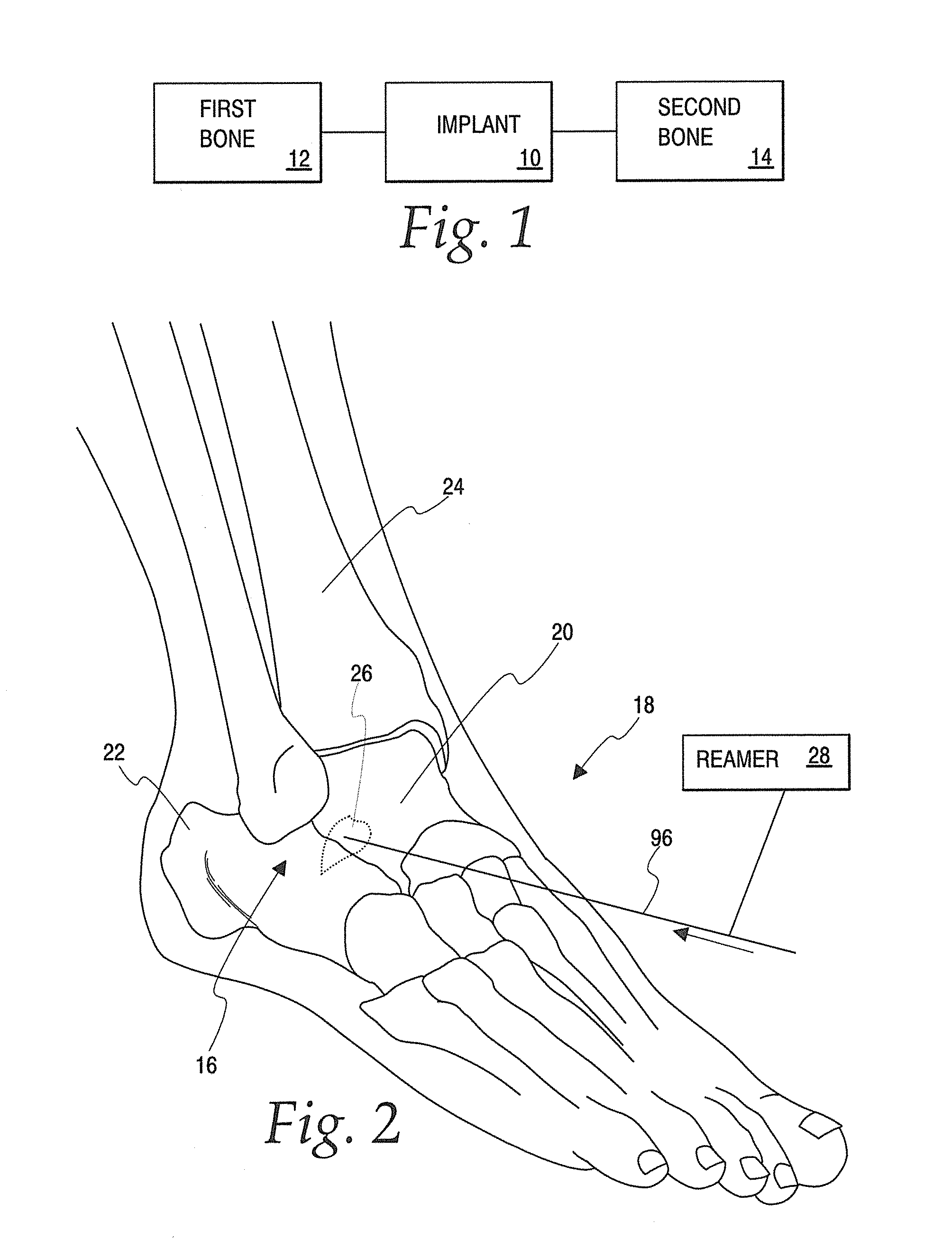
[0076]In FIG. 1, there is a generic showing of the inventive implant 10 used to fix first and second bones 12, 14, respectively. The implant 10 and bones 12, 14 are shown schematically to cover the full breadth of the invention. The schematic showing of the implant 10 is intended to encompass all versions, as described herein, and virtually an unlimited number of variations thereof that would be apparent to one skilled in the art from the disclosure herein. The first and second bones 12, 14 are shown schematically to include specific bones for which the implant 10 is particularly adapted, as described hereinbelow, and bones at any site in the human body that might be fixed consistently with the principles described herein.

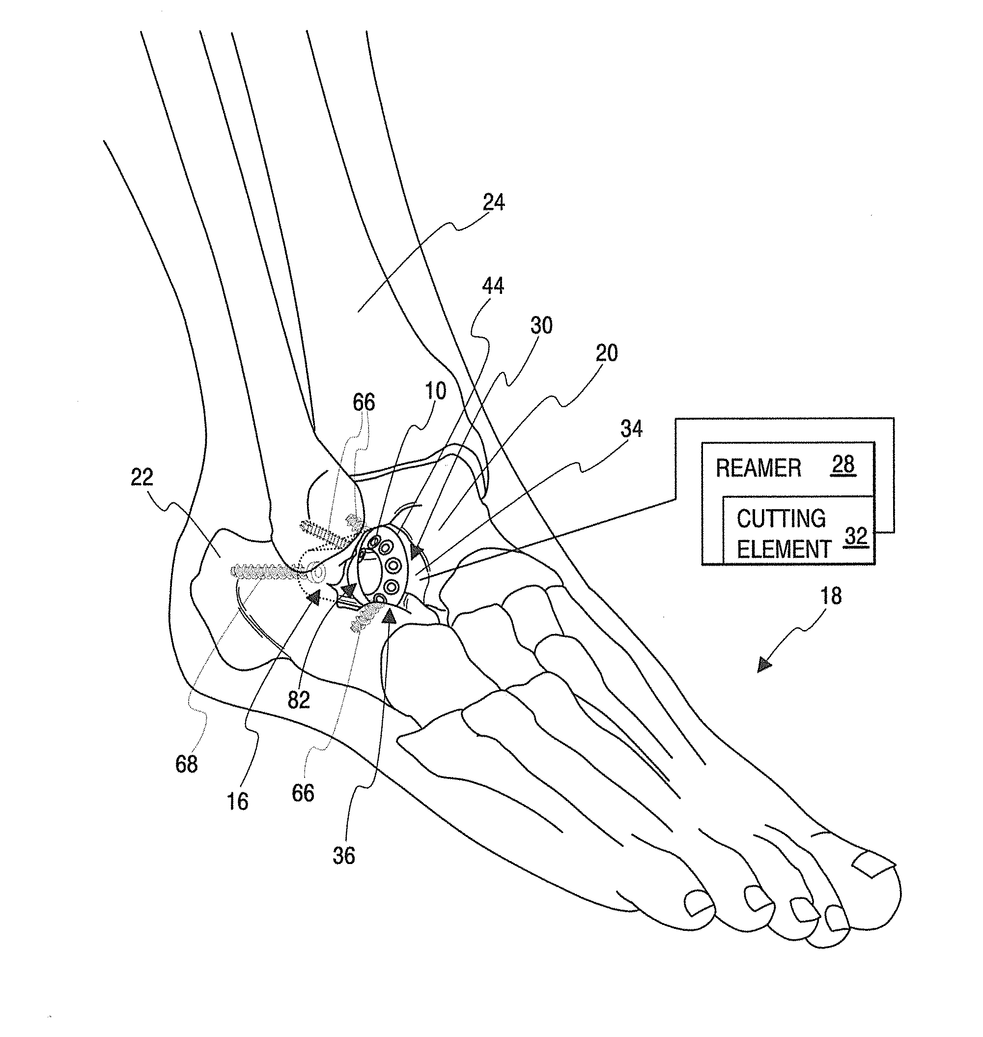
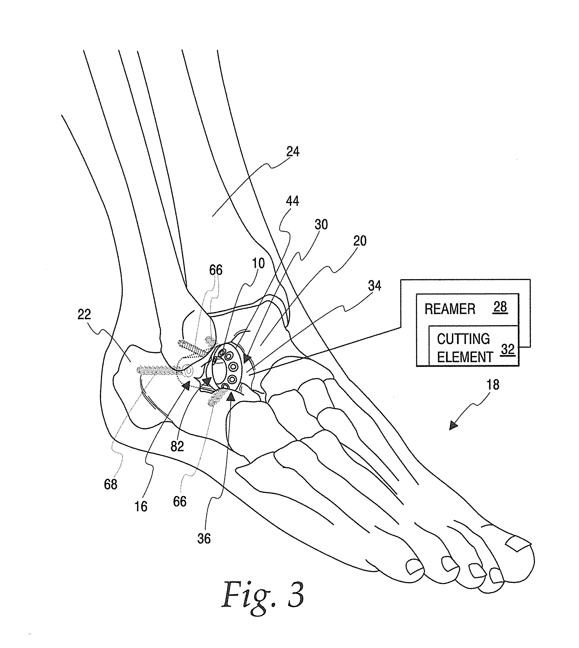
[0077]The invention will be described herein as used at the subtalar joint at 16 on a human foot at 18, as shown in FIGS. 2-4. The subtalar joint 16 is located where the talus 20 sits on top of the calcaneus 22. The tibia 24 is situated on top of the talus 20. A co...


PUM


Abstract

An implant for fixation of first and second bones having a body with first and second axially spaced ends and an outer surface at least nominally matched to a tapered surface around a receptacle formed by rotating a cutting element around an axis. As the body is advanced along the central axis into an operative position within the receptacle, the body outer surface and tapered surface cooperate to cause the central and second axes to consistently substantially align. A plurality of openings in the body each accepts a fastener.

Description

BACKGROUND OF THE INVENTION[0001]1. Field of the Invention[0002]This invention relates to implants and, more particularly, to an implant for fixation of first and second bones, as to allow fusion therebetween. The invention is also directed to a method of fixing first and second bones using the implant.[0003]2. Background Art[0004]It is known to fuse the talus and the calcaneus (the “heel bone”) to address certain foot conditions. The talus sits on top of the calcaneus. Superiorly (on its upper surface), the talus forms a major part of the ankle joint, this joint providing the motion that allows the foot to go up and down. Inferiorly (on its lower surface), the talus forms a separate joint with the calcaneus, the subtalar joint. The subtalar joint is actually not a single joint surface but rather formed by three separate and distinct facets, with the posterior facet being the major part and the anterior and middle facets small contributions to this joint. The three joints work toget...

Claims


Application Information

Patent Timeline
IPC IPC(8): A61F2/42A61F2/46
CPCA61F2/4202A61F2/4606A61B17/86A61F2002/30217A61F2002/30772A61F2002/4223A61F2002/2835A61F2002/302A61F2002/3021A61F2002/30622A61F2002/30688A61F2002/30782A61F2002/30784A61F2002/30807A61F2002/4207A61F2002/4217
Inventor SCHMIDT, GARY J.RILEY, JAMIE
Owner TRIMED
Learn More