

Cloud service recovery time prediction system, method and program
a prediction system and service technology, applied in the field of cloud service recovery time prediction system, cloud service recovery time prediction method, and a, can solve the problems of hundreds of thousands of users being affected by a partial system failure, user cannot directly control failure recovery processing, and the number of users affected by a service failure also increases
- Summary
- Abstract
- Description
- Claims
- Application Information
AI Technical Summary
Benefits of technology
Problems solved by technology
Method used
Image

Examples
exemplary embodiment 1
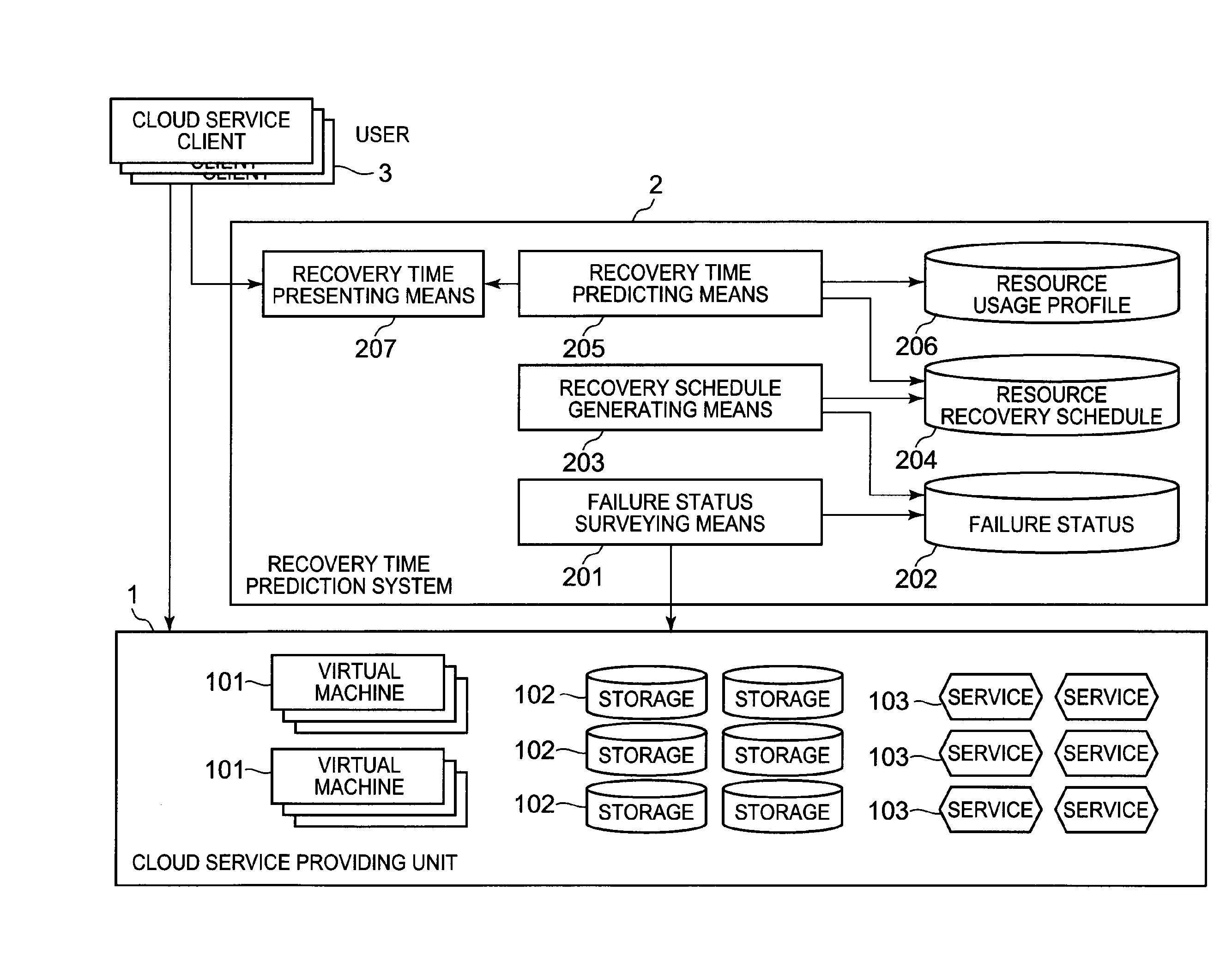
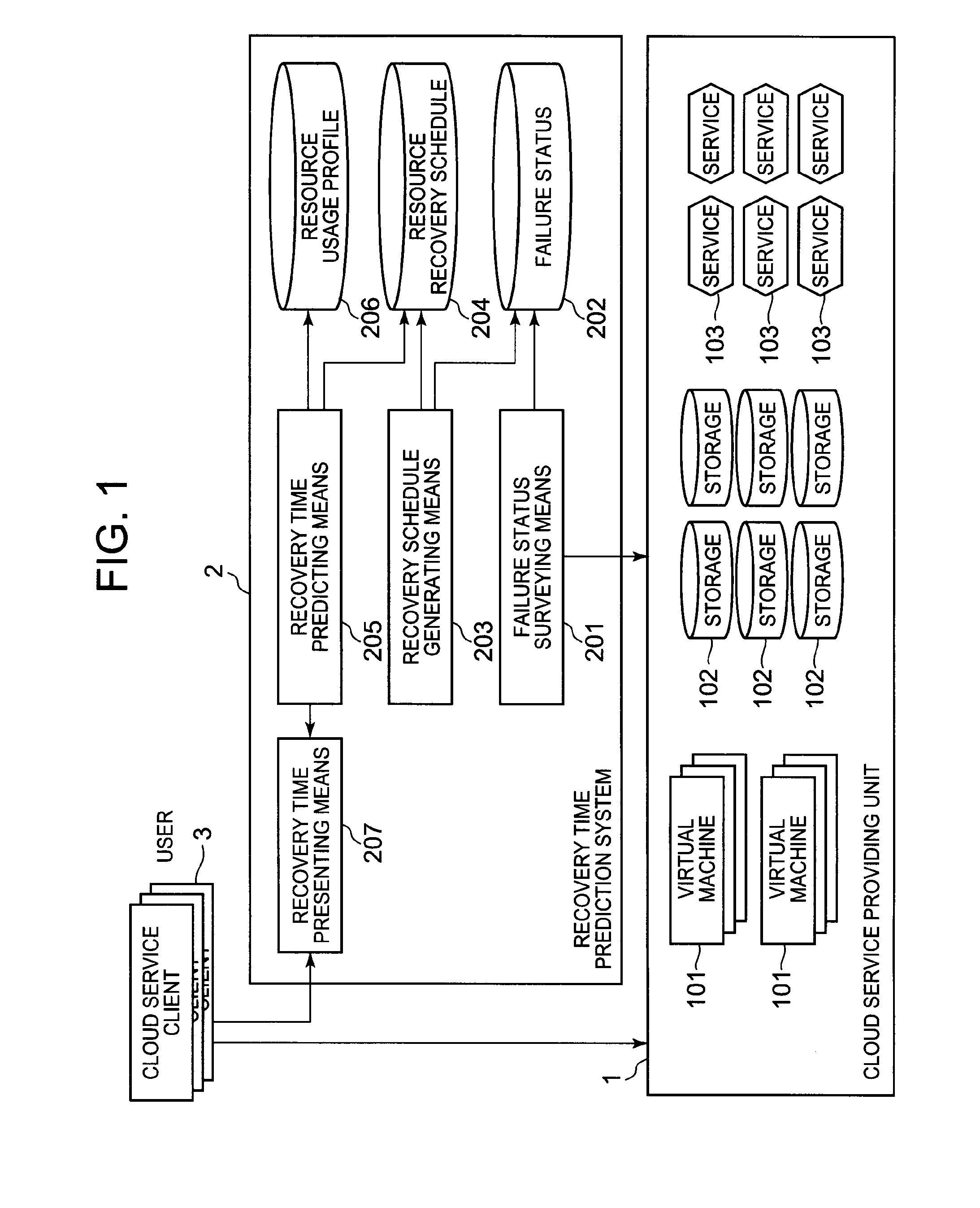
[0045]FIG. 1 is an illustration diagram illustrating an example of an entire configuration of a cloud service including a cloud service recovery time prediction system according to a first exemplary embodiment of the invention. The cloud service illustrated in FIG. 1 includes a cloud service providing unit 1, a recovery time prediction system 2, and a cloud service client 3. The recovery time prediction system 2 illustrated in FIG. 1 corresponds to the cloud service recovery time prediction system according to the first exemplary embodiment of the invention. The cloud service providing unit 1, the recovery time prediction system 2, and the cloud service client 3 are connected to each other through a communication network (not illustrated).
[0046]The cloud service providing unit 1 includes a virtual machine 101, a storage 102, and a service providing unit 103. The virtual machine 101, the storage 102, and the service providing unit 103 are used to provide various services to a user. I...
exemplary embodiment 2
[0081]Next, a cloud service recovery time prediction system according to a second exemplary embodiment of the invention will be described. Also, the cloud service recovery time prediction system according to the second exemplary embodiment is also included in the same configuration as the cloud service illustrated in FIG. 1. FIG. 4 is an illustration diagram illustrating an example of the cloud service recovery time prediction system according to the second exemplary embodiment of the invention. In addition, the same configurations as in the first exemplary embodiment will be denoted by the same reference numerals as in FIG. 1, and a description thereof will be omitted. A recovery time prediction system 2 according to the second exemplary embodiment includes a resource reservation information storing unit 208 in addition to the configuration of the recovery time prediction system 2 according to the first exemplary embodiment.
[0082]Among the computing resources of a cloud service pro...
exemplary embodiment 3
[0102]Next, a cloud service recovery time prediction system according to a third exemplary embodiment of the invention will be described. Also, the cloud service recovery time prediction system according to the third exemplary embodiment is also included in the same configuration as the cloud service illustrated in FIG. 1. FIG. 6 is an illustration diagram illustrating an example of the cloud service recovery time prediction system according to the third exemplary embodiment of the invention. In addition, the same configurations as in the first exemplary embodiment will be denoted by the same reference numerals as in FIG. 1, and a description thereof will be omitted. A recovery time prediction system 2 according to the third exemplary embodiment includes a recovery schedule optimizing means 209 and a recovery schedule constraint information storing unit 210 in addition to the configuration of the recovery time prediction system 2 according to the first exemplary embodiment.
[0103]The...
PUM
 Abstract
Description
Claims
Application Information