
Air conditioner for vehicle

a technology for air conditioners and vehicles, applied in the direction of domestic cooling devices, defrosting, applications, etc., can solve the problems of increasing the power consumption of compressors, difficult to accurately determine whether or not an external heat exchanger is working properly, and the time required to defrost an external heat exchanger is considerable, so as to reduce the travelling wind speed, reduce the amount of cold air, and reduce the effect of cold air

Active Publication Date: 2013-11-21
HONDA MOTOR CO LTD
View PDF1 Cites 24 Cited by
  • Summary
  • Abstract
  • Description
  • Claims
  • Application Information

AI Technical Summary

Benefits of technology

The present invention provides an air conditioner for a vehicle that is able to efficiently defrost in a short space of time. It is able to switch between a cooling operation and a hot gas operation to limit the amount of cold air and maximize the amount of heat released during the defrosting process. Additionally, the air conditioner can detect the reduction in the traveling wind speed of the external heat exchanger to determine whether or not frost formation has occurred and initiate the defrosting mode operation accordingly.

Problems solved by technology

However, in a defrosting operation that uses hot gas, because the hot gas is generated by the heat generated by the compressor itself being transmitted to the heat exchange medium, the problems arise that the power consumption of the compressor is increased, and a considerable length of time is needed until the frost begins to melt.
However, in actuality, it is difficult to accurately determine whether or not the external heat exchanger is in a frosted state solely from the surface temperature of the external heat exchanger, and in order to ensure a desired determination accuracy, there is a possibility that a determination that is based on an enormous amount of actual measurement data that will have to be obtained by combining a plurality of other parameters such as, for example, the outside air temperature and the vehicle speed and the like will be needed.
Moreover, if the defrost mode operation is executed based solely on information of temperature such as the surface temperature of the external heat exchanger, then if, in actual fact, the external heat exchanger is not in a frosted state, or if the external heat exchanger is in a frosted state but the performance of the external heat exchanger has not deteriorated, then there is a possibility that the defrosting mode operation will be executed excessively frequently.

Method used


Image

  • Air conditioner for vehicle
  • Air conditioner for vehicle
  • Air conditioner for vehicle

Examples


first embodiment

(Method of Performing a Defrosting Operation in a Air Conditioner for a Vehicle: First Embodiment)

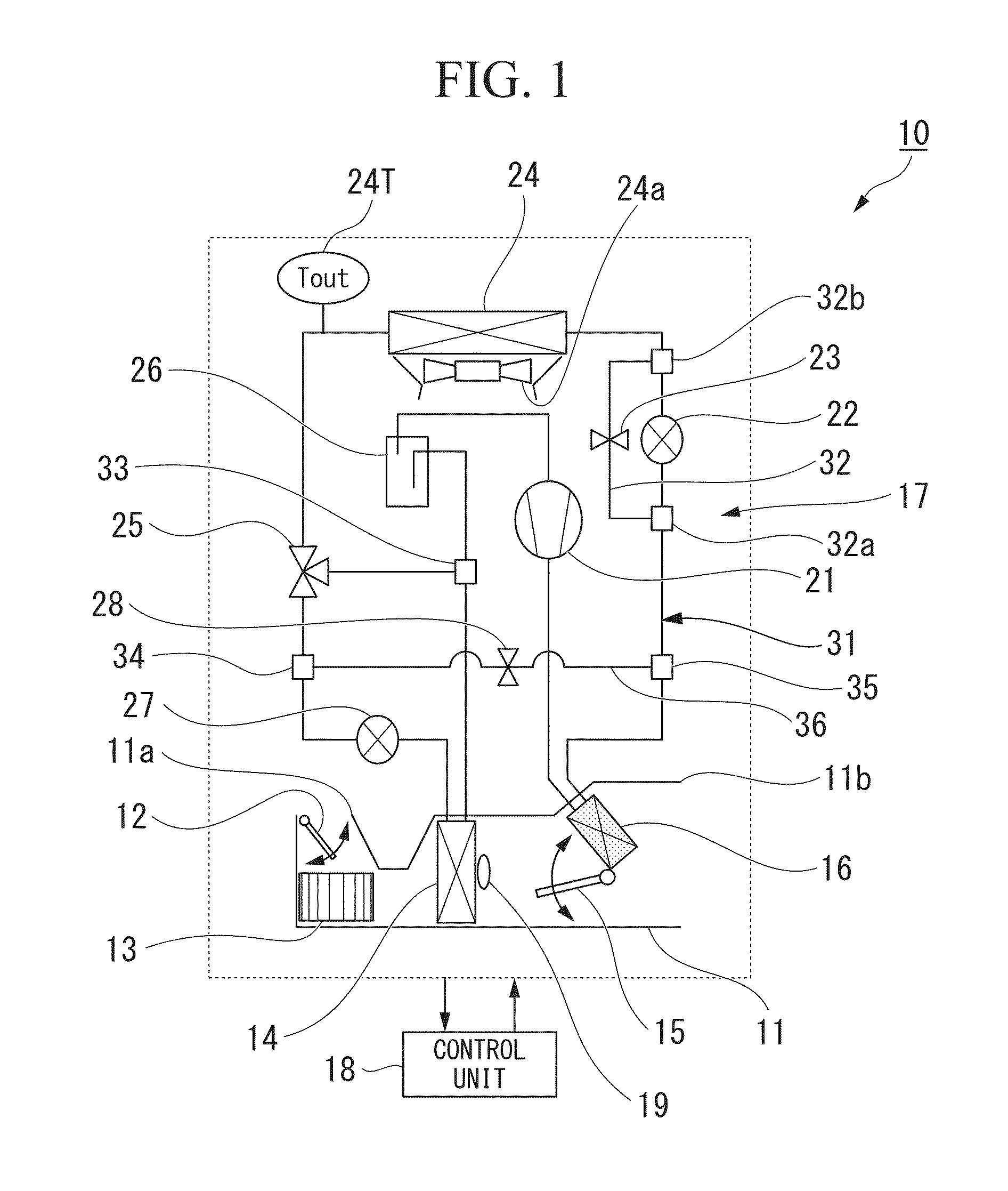
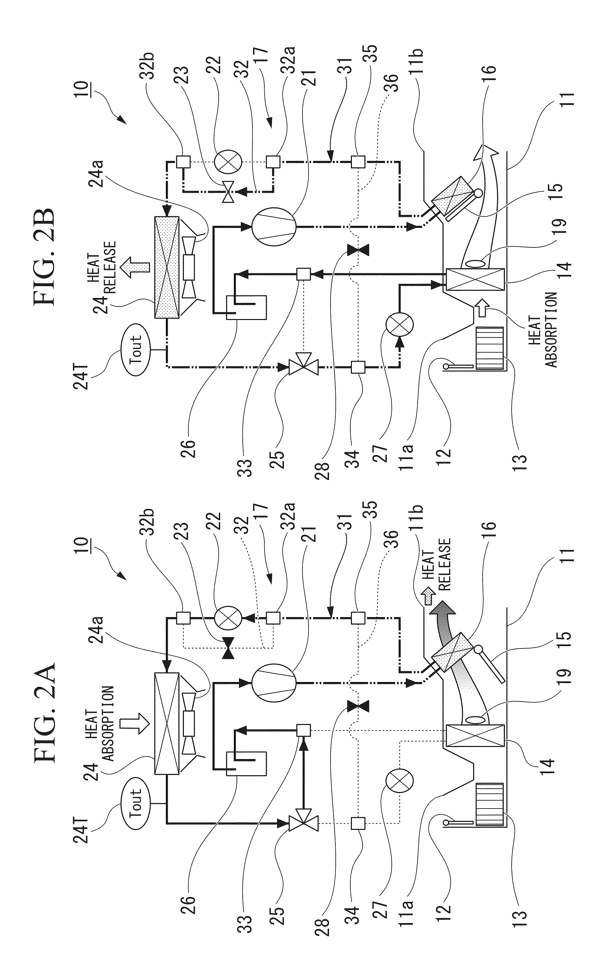
[0101]FIG. 5 is a flowchart showing a method of performing a defrosting operation in an air conditioner for a vehicle according to a first embodiment, while FIG. 6 is a timing chart for the same. In the method of performing a defrosting operation in the air conditioner for a vehicle according to the first embodiment, the control unit 18 firstly performs a defrosting cooling operation, and then subsequently performs a hot gas operation.

[0102]The method of performing a defrosting operation of the first embodiment starts from a warming mode operation state (S5).

[0103]Next, a defrosting determination is performed in order to determine whether or not frost formation has occurred on the external heat exchanger 24 (i.e., to determine whether or not defrosting is necessary) (S10).

[0104]Specifically, the external air temperature ‘Tam’ is measured by an external temperature sensor (not shown), an...

second embodiment

(Method of Performing a Defrosting Operation in an Air Conditioner for a Vehicle: Second Embodiment)

[0126]FIG. 7 is a flowchart showing a method of performing a defrosting operation in an air conditioner for a vehicle according to a second embodiment, while FIG. 8 is a timing chart for the same. In the method of performing a defrosting operation in the air conditioner for a vehicle according to the second embodiment, the control unit 18 firstly performs a hot gas operation, and then performs a defrosting cooling operation, and then subsequently performs a hot gas operation once again. Note that no description is given of portions that have the same structure as in the first embodiment.

[0127]In the same way as in the first embodiment, this routine starts from a warming mode operation state (S5), and then a defrosting determination is performed in order to determine whether or not frost formation has occurred on the external heat exchanger 24 (i.e., to determine whether or not defrost...


PUM


Abstract

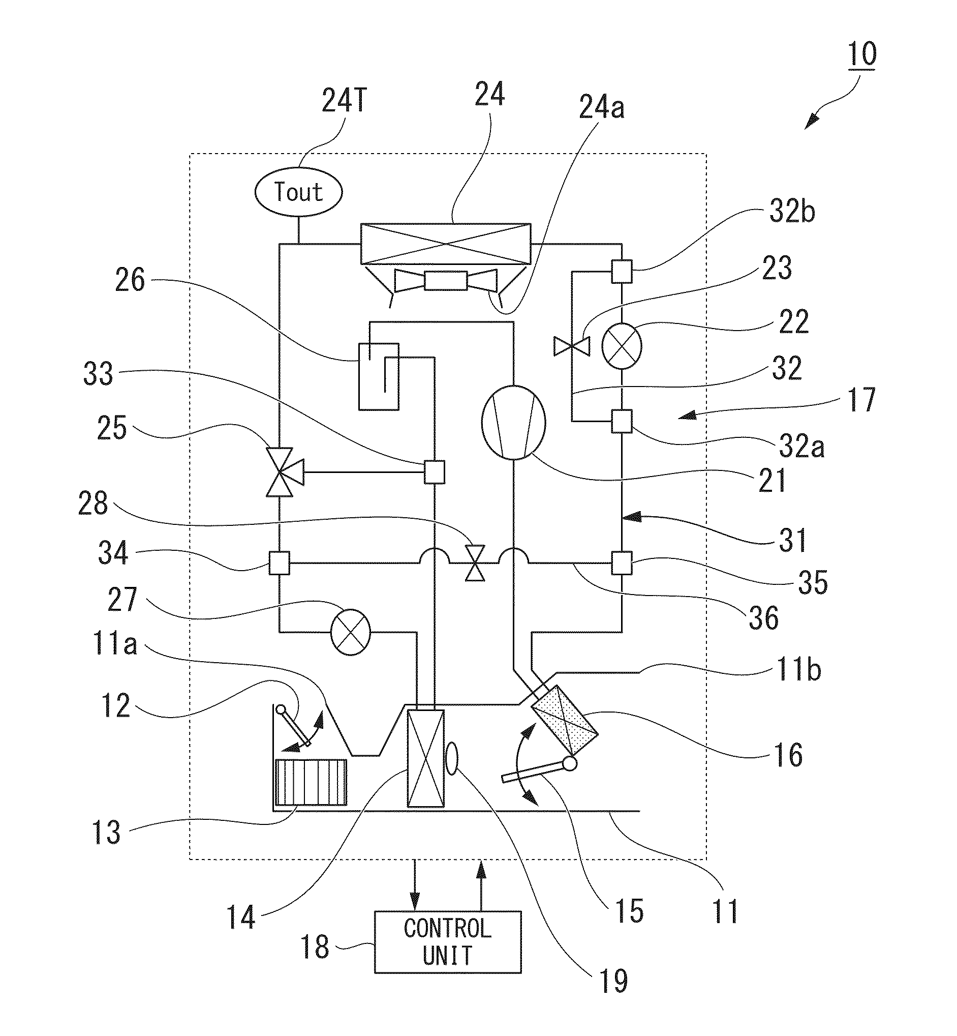
An air conditioner for a vehicle is provided with: a compressor that compresses a heat exchange medium; an external heat exchanger that receives the heat exchange medium and that exchanges heat with the outside of a vehicle compartment; and an evaporator that receives the heat exchange medium and exchanges heat with the inside of a vehicle compartment, and the air conditioner for a vehicle is able to perform: a defrosting cooling operation in which the heat exchange medium that has been compressed by the compressor is made to flow into the evaporator and absorb heat, and to then flow into the external heat exchanger and release heat; and a hot gas operation in which the heat exchange medium that has been compressed by the compressor is made to flow into the external heat exchanger and release heat without being made to absorb heat in the evaporator, and, by switching between performing the defrosting cooling operation and performing the hot gas operation, the air conditioner for a vehicle performs a defrosting operation in which the external heat exchanger is defrosted.

Description

[0001]Priority is claimed on Japanese Patent Application No. 2012-115561, filed May 21, 2012 and Japanese Patent Application No. 2012-115564, filed May 21, 2012, the contents of which are incorporated herein by reference.BACKGROUND OF THE INVENTION[0002]1. Field of the Invention[0003]The present invention relates to an air conditioner for a vehicle.[0004]2. Description of Related Art[0005]In electric vehicles, because the engine cooling water cannot be used to heat the vehicle interior, an air conditioner for a vehicle that utilizes a heat pump cycle is employed (see, for example, Japanese Unexamined Patent Application Publication (JP-A) Nos. 5-310034 and 2000-343934). In addition to a compressor, this air conditioner for a vehicle is provided with a heating expansion valve and an external heat exchanger, and also with a cooling expansion valve and an internal heat exchanger.[0006]During a warming operation, a heat exchange medium that has been compressed by the compressor is expand...

Claims


Application Information

Patent Timeline
IPC IPC(8): F25D21/00
CPCF25D21/004B60H1/00921B60H1/321F25B47/022B60H2001/00961
Inventor TSUNODA, ISAOICHIKAWA, KAZUMA
Owner HONDA MOTOR CO LTD
Learn More