Device for dispensing an additive

a technology of additives and devices, applied in the direction of liquid fuel feeders, machines/engines, mechanical apparatus, etc., can solve the problems of insufficient efficiency in regenerating pf in order, insensitive to fuel quality, and inability to supply the vehicle with fuel of good quality. , to achieve the effect of compact siz

Active Publication Date: 2013-11-21
FILTRAUTO +1
View PDF1 Cites 23 Cited by
  • Summary
  • Abstract
  • Description
  • Claims
  • Application Information

AI Technical Summary

Benefits of technology

[0045]One advantage of the invention lies in the fact that it allows integrating an additive distributor into the design of new engines as well as into existing engines.
[0046]Another advantage of the invention lies in the possibility of being able to release a defined quantity of additive in a precise manner.
[0047]Another advantage of the invention lies in the possibility of being able to release multiple types of additive regardless of their composition and / or their physicochemical properties.
[0048]Another advantage of the invention lies in the ability to control the release of the additive as a function of various parameters.
[0049]Another advantage of the invention lies in its compact size.

Problems solved by technology

New engine technologies, such as diesel engines with a common rail and a very high pressure fuel injection system, offer high performance but are very sensitive to fuel quality.
The quality of available commercial fuels does not always allow supplying the vehicle with fuel of good quality, even when enhanced with additives.
It is no longer sufficient to efficiently regenerate the PF in order to stop the black smoke and soot.
Similarly, the ECU management of the system also plays a large role in the cost of the complete system.
The use of such a strategy also involves properly controlling the dosing system and verifying its state, which is particularly intrusive when managing vehicle failure modes.
In terms of maintenance, filling the reservoir is fairly difficult and is done through a connector adapted for the filling requirements and for the additive reservoir.
In certain geographical regions, such as the developing countries, it is difficult to guarantee that the reservoir will be properly filled throughout the life of the vehicle.
This technical solution has the disadvantage of requiring an additive reservoir of significant volume as well as an electronic system for measuring the filling of the fuel tank.
In addition, this technical solution increases the weight of the vehicle, and therefore its fuel consumption.
This technical solution has the disadvantage of the additive being dissolved or diluted by the fuel introduced into the additive reservoir, which does not allow controlling the concentration of the additive released into the fuel.

Method used


Image

  • Device for dispensing an additive
  • Device for dispensing an additive
  • Device for dispensing an additive

Examples


Embodiment Construction

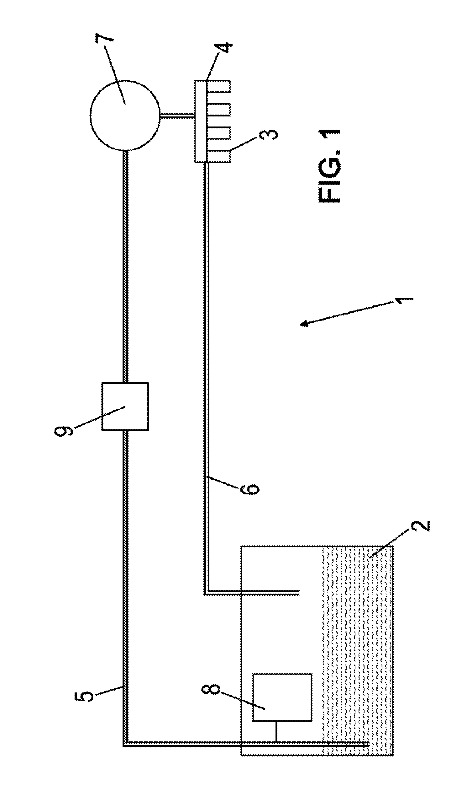
[0056]FIG. 1 schematically represents a fuel circulation circuit 1 for an internal combustion engine. Conventionally, the fuel circulation circuit 1 is arranged between a fuel tank 2 and the high-pressure fuel rail 4 (also called a “common rail”) and ensures the circulation of the fuel between the interior of the fuel tank and the common rail. The fuel supply circuit includes a filter 9 for filtering the fuel and a high-pressure pump 7. The high-pressure pump 7 and the common rail 4 constitute the fuel injection system. A first line 5, called the supply line, allows the fuel to circulate from inside the tank 2 to the common rail 4, and a second line 6, called the return line, allows the fuel to circulate from the injection system to inside the tank 2. The fuel is therefore pumped into the tank 2, then filtered in the filter 9, is sent under pressure to the common rail 4 by means of the pump 7, then part is directed toward the engine injectors 3 and part is returned to inside the tan...


PUM


Abstract

The invention relates to a device for dispensing a liquid additive into a fuel circulation circuit for an internal combustion engine, comprising a reservoir (12) of liquid additive allowing an additive to be distributed into the fuel circulation circuit by means of a distribution line (16), characterized in that it comprises an additive chamber (22) in communication with the fuel circulation circuit and at least one wall (32) that is mobile and fluidtight between said additive chamber and the additive reservoir which, on the one hand, provides a fluidtight division and, on the other hand, maintains equal pressure between the additive in the additive reservoir and the fuel in the additive chamber.

Description

TECHNICAL FIELD OF THE INVENTION[0001]The technical field of the invention is that of internal combustion engines, particularly motor vehicle engines, and more particularly the field of devices for dispensing a liquid additive into the fuel circulation circuit of an internal combustion engine.TECHNOLOGICAL BACKGROUND OF THE INVENTION[0002]New engine technologies, such as diesel engines with a common rail and a very high pressure fuel injection system, offer high performance but are very sensitive to fuel quality. There is therefore a benefit to using a fuel containing additives to improve its quality, such as additives to improve fuel distribution in the engine, additives to improve engine performance, and additives to improve engine operation stability. The quality of available commercial fuels does not always allow supplying the vehicle with fuel of good quality, even when enhanced with additives.[0003]Furthermore, in order to meet new vehicle emission standards, especially for di...

Claims


Application Information

Patent Timeline
Patent Type & Authority Applications(United States)
IPC IPC(8): F02M25/00F02M37/32
CPCF02M25/00C10L1/02C10L1/04C10L1/2222C10L1/301C10L1/305F01N2430/04F02M37/0064B01J4/001B01J8/0015B01J8/006B01J2204/002B01J2208/00752B01J2208/00769C10L2290/141C10L2200/0245C10L2250/06C10L2200/024C10L1/10C10L1/1208C10L1/1233C10L1/1608C10L1/1881C10L1/238C10L10/00C10L10/02C10L10/06C10L10/08C10L2290/547C10L2230/04C10L2290/56F02M37/32F02M37/22
Inventor MONSALLIER, GUYHARLE, VIRGINIEHORBEZ, DOMINIQUELALLEMAND, MICHAEL
Owner FILTRAUTO
Why Eureka
Try Eureka