Blood pressure measuring device

a blood pressure and measuring device technology, applied in the field of blood pressure measuring devices, can solve the problems of easy corruption of noise, difficult measurement in many cases, etc., and achieve the effects of accurate blood pressure, short time, and high accuracy

Inactive Publication Date: 2013-11-21
DENSO CORP
View PDF4 Cites 16 Cited by
  • Summary
  • Abstract
  • Description
  • Claims
  • Application Information

AI Technical Summary

Benefits of technology

[0007]The present disclosure provides a blood pressure measuring device capable of actualizing an operating system that allows acquisition of measurement information required for calculation of blood pressure to be started while a casing configuring the blood pressure measuring device is being held.
[0009]In the blood pressure measuring device of the present disclosure, acquisition of measurement information required for calculation of blood pressure is started while the user is holding the casing of the blood pressure measuring device in both hands and contact is maintained between the hands and the corresponding electrocardiographic electrodes and pulse wave sensor. In other words, the palms and fingers holding the casing do not need to be repositioned when the measuring section starts acquisition of the measurement information. Therefore, electrocardiographic signals and pulse wave signals can be measured with high accuracy. Accurate blood pressure can be obtained in a short amount of time.

Problems solved by technology

Noise tends to corrupt electrocardiograms and the pulse waves depending on changes in the state of contact with the electrodes and the pulse wave sensor.
Measurement becomes difficult in many cases.

Method used


Image

  • Blood pressure measuring device
  • Blood pressure measuring device
  • Blood pressure measuring device

Examples


first exemplary embodiment

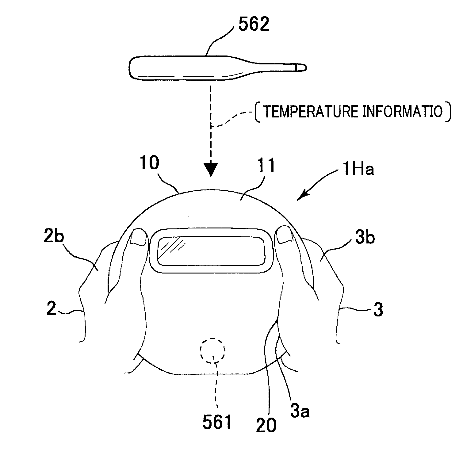
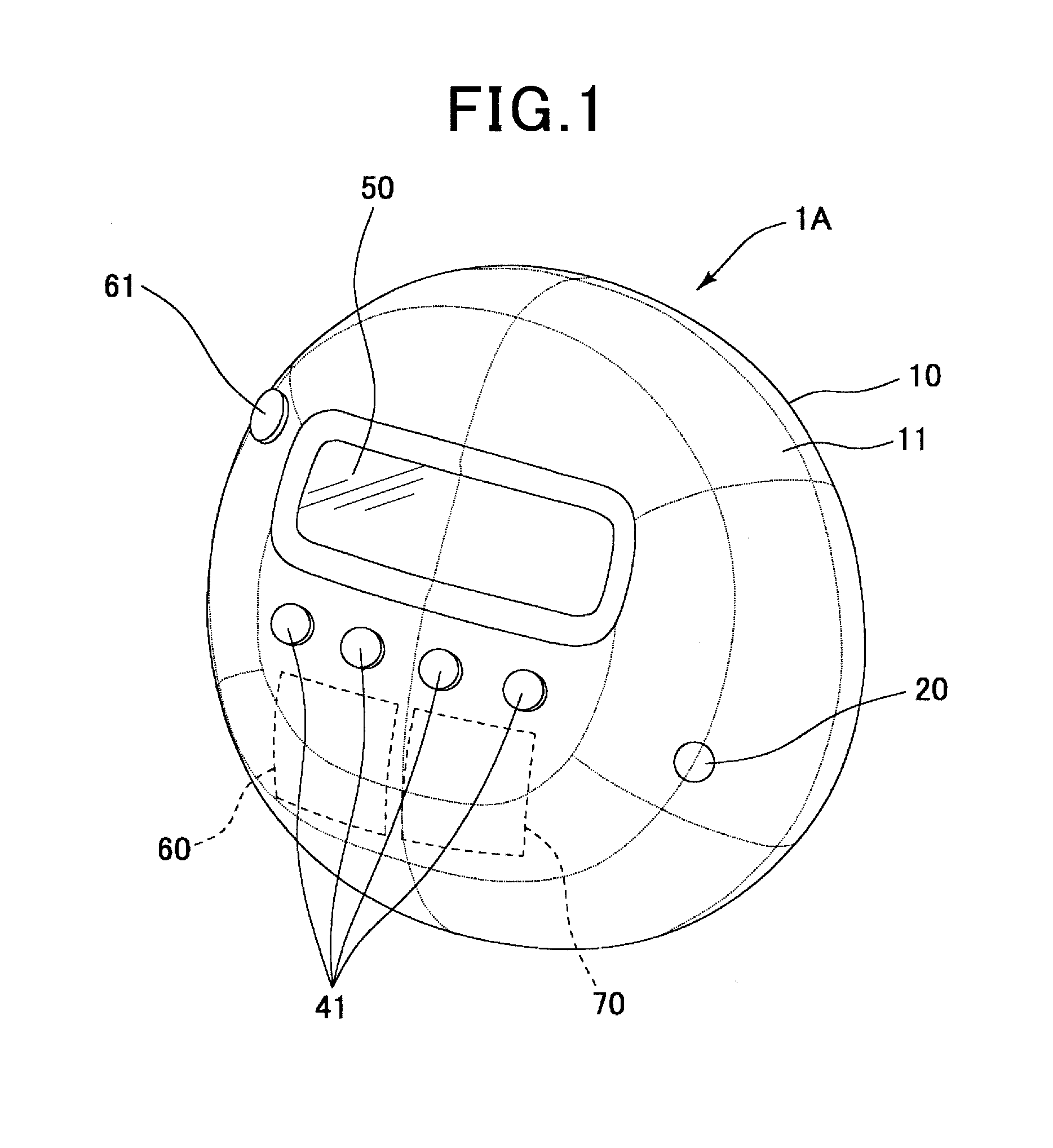
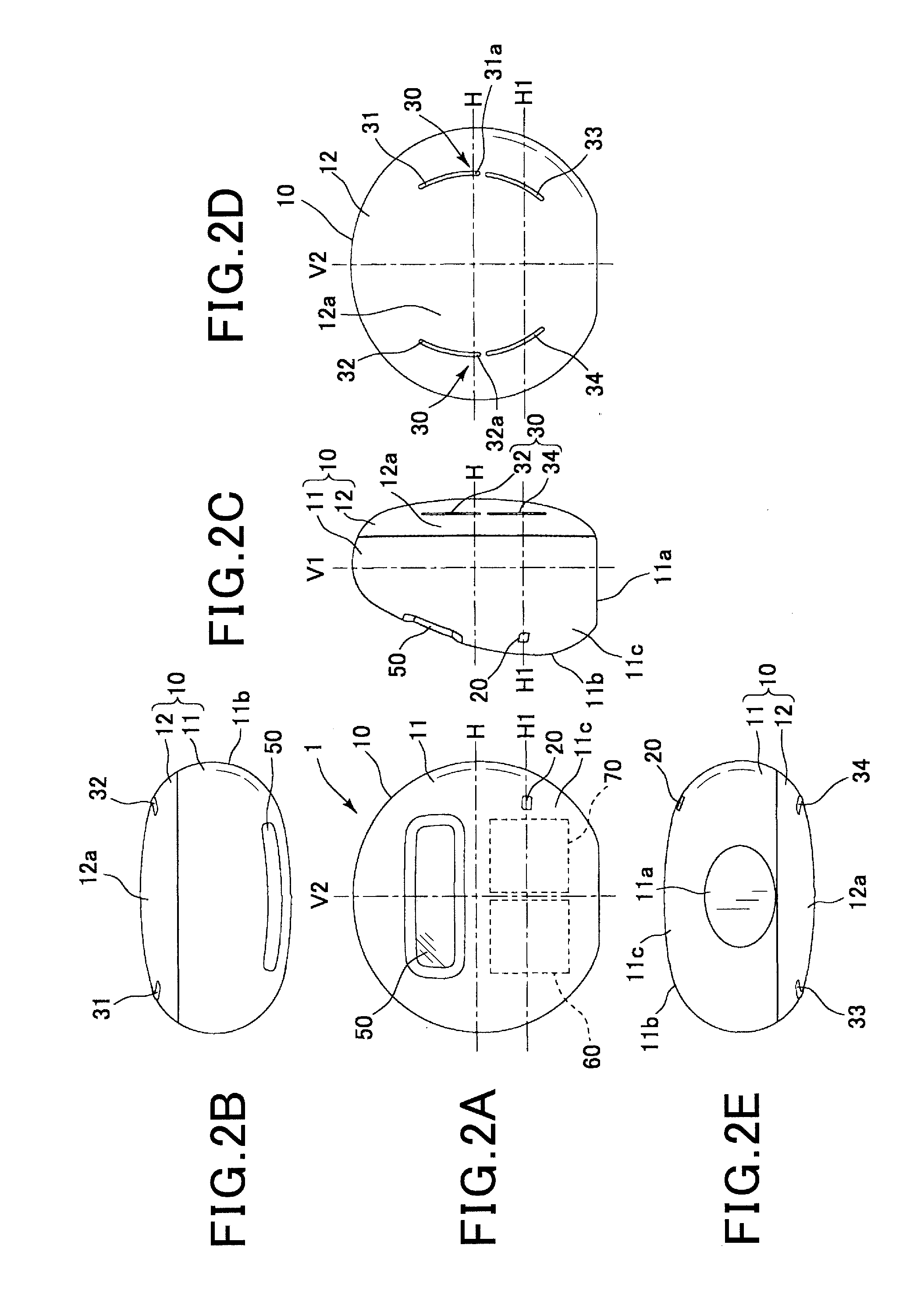
[0041]A blood pressure measuring device 1A provides a function for detecting electrocardiographic signals and pulse wave signals of a user (measurement subject), a function for acquiring measurement information based on the electrocardiographic signals and pulse wave signals, a function for calculating blood pressure using the measurement information, and a function for displaying the calculated blood pressure. As shown in FIG. 1 to FIG. 3A and FIG. 3B, the blood pressure measuring device 1A includes a casing 10, a pulse wave sensor 20, electrocardiographic electrodes 30, information input buttons 41, a display section 50, a measurement circuit 60, an operating button 61, and a calculation circuit 70. Illustration of the operating system (manipulating system), such as the information input buttons 41 and the operating button 61, is omitted in FIG. 2A to FIG. 2E, FIG. 3A and FIG. 3B.

[0042]The casing 10 is formed into a spherical shape. Here, “spherical shape” in the present specifica...

second exemplary embodiment

[0076]According to the above-described first exemplary embodiment, the operating button 61 is provided in a position allowing contact with the palm 2a, the pointer finger 2b, or the thumb 2c of the left hand 2. However, instead, a configuration is possible in which an operating button 161 is provided on the bottom surface 11a of the casing 10 as shown, for example, in a blood pressure measuring device 1E in FIG. 16. In FIG. 16, illustration of the information input buttons 41 is omitted. Other configurations are the same as those according to the first exemplary embodiment. Therefore, components and sections corresponding with those according to the first exemplary embodiment are given the same reference numbers. Explanations thereof are omitted.

[0077]The operating button 161 is biased in a direction projecting from the bottom surface 11a of the casing 10. When the casing 10 is placed on a surface 5 of a desk, a floor, or the like with the bottom surface 11a on the bottom side while...

third exemplary embodiment

[0090]Instead of the configurations according to the first and second exemplary embodiments, a configuration is also possible in which an operating button 261 is located on the top surface of the casing 10 as shown, for example, in a blood pressure measuring device 1F in FIG. 18. In FIG. 18, illustration of the information input buttons 41 is omitted. Other configurations are the same as those according to the above-described first exemplary embodiment. Therefore, components and sections corresponding with those according to the first exemplary embodiment are given the same reference numbers. Explanations thereof are omitted.

[0091]The operating button 261 is provided in a position that is difficult to press and operate by the user himself who is holding the casing 10, but can be easily pressed and operated by a hand 4 of a third party such as a doctor or a nurse. In other words, the operating button 261 is provided in the upper portion of the casing 10 that cannot be pressed by the ...


PUM


Abstract

In a blood pressure measuring device, a casing is held in both hands. A pair of electrocardiographic electrodes are respectively provided to allow contact with the hands holding the casing, and detect electrocardiographic signals through the hands. A pulse wave sensor is provided to allow contact with either of the hands holding the casing, and detects pulse wave signals through the hand. Based on these detected signals, a measuring section acquires measurement information including: a time difference between an electrocardiographic R wave and a pulse wave reference point; and a pulse wave amplitude. A calculating section calculates blood pressure using the measurement information. A display section displays the blood pressure. A measurement starting section enables the measuring section to start acquisition of the measurement information in a state in which contact is maintained between the hands holding the casing and the corresponding electrocardiographic electrodes and pulse wave sensor.

Description

CROSS-REFERENCE TO RELATED APPLICATION[0001]This application is based on and claims the benefit of priority from earlier Japanese Patent Application No. 2012-104496 filed May 1, 2012, the description of which is incorporated herein by reference.BACKGROUND[0002]1. Technical Field[0003]The present invention relates to a blood pressure measuring device.[0004]2. Related Art[0005]As this type of measuring device, a health management index advising apparatus is known that includes electrodes for applying current and electrodes for measuring voltage in correspondence with both hands (for example, refer to JP-A-H10-174680). Specifically, the health management index advising apparatus measures body fat. Impedance in the body is calculated based on electric potential received from both electrodes for measuring voltage. A measurement starting switch is provided in a tip portion of the electrode for applying current on the right-thumb side. The measurement starting switch serves as a trigger fo...

Claims


Application Information

Patent Timeline
Patent Type & Authority Applications(United States)
IPC IPC(8): A61B5/0404A61B5/01A61B5/0456A61B5/0205A61B5/0408A61B5/04A61B5/332A61B5/352
CPCA61B5/0404A61B5/04085A61B5/04012A61B5/0456A61B5/02055A61B5/01A61B5/02125A61B2560/0209A61B2560/0425A61B2560/0468A61B2562/046A61B5/332A61B5/282A61B5/352A61B5/316
Inventor KAWACHI, TAIJIOHOKA, TADAO
Owner DENSO CORP
Why Eureka
Try Eureka