Shape measuring apparatus

Active Publication Date: 2013-11-21
MITUTOYO CORP
View PDF11 Cites 22 Cited by
  • Summary
  • Abstract
  • Description
  • Claims
  • Application Information

AI Technical Summary

Benefits of technology

[0021]When the stylus tip is moved so as to scan the surface of a workpiece to be measured, there may generate an event that a displacement direction of the probe does not coincide with a normal direction of the workpiece due to friction between the stylus tip and the workpiece. Therefore, if a push correction vector is calculated using a probe displacement direction as a push direction, the probe may be moved in an unintended

Problems solved by technology

However, no consideration is given to a variation of the amount of the push of a probe toward a workpiece to be measured.
This means a problem that the measurement accuracy is lowered.
This means a problem of a long measurement time.
In this case, if the speed in the scanning direction

Method used


Image

  • Shape measuring apparatus
  • Shape measuring apparatus
  • Shape measuring apparatus

Examples


embodiment

Advantages of Embodiment

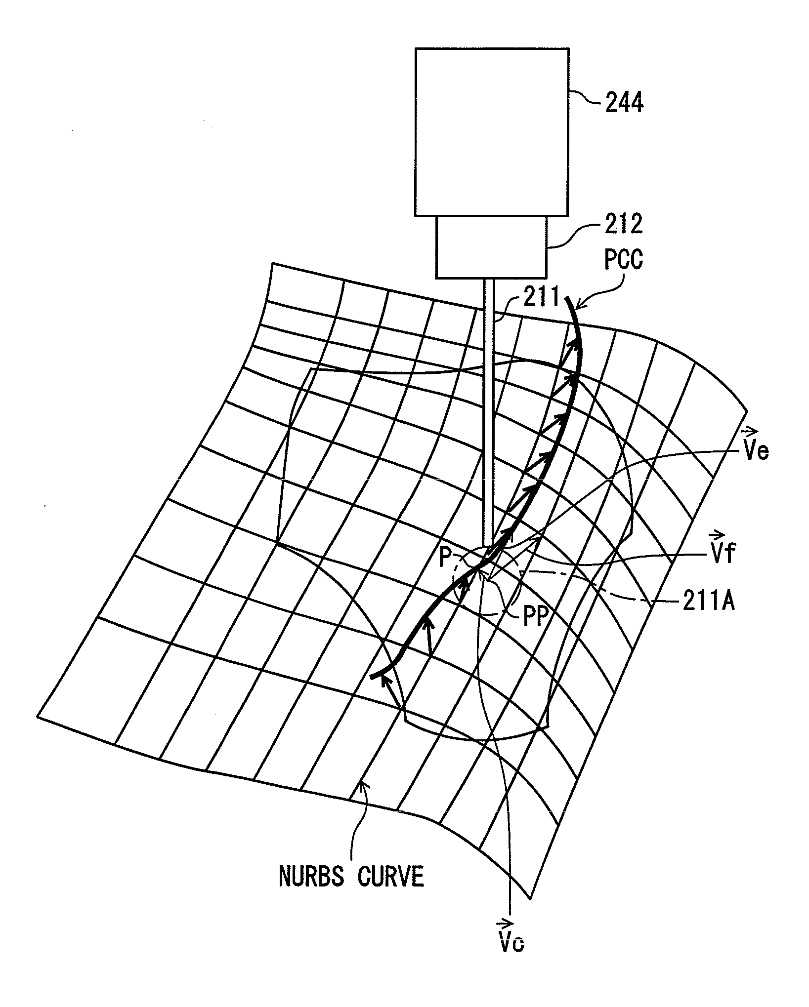
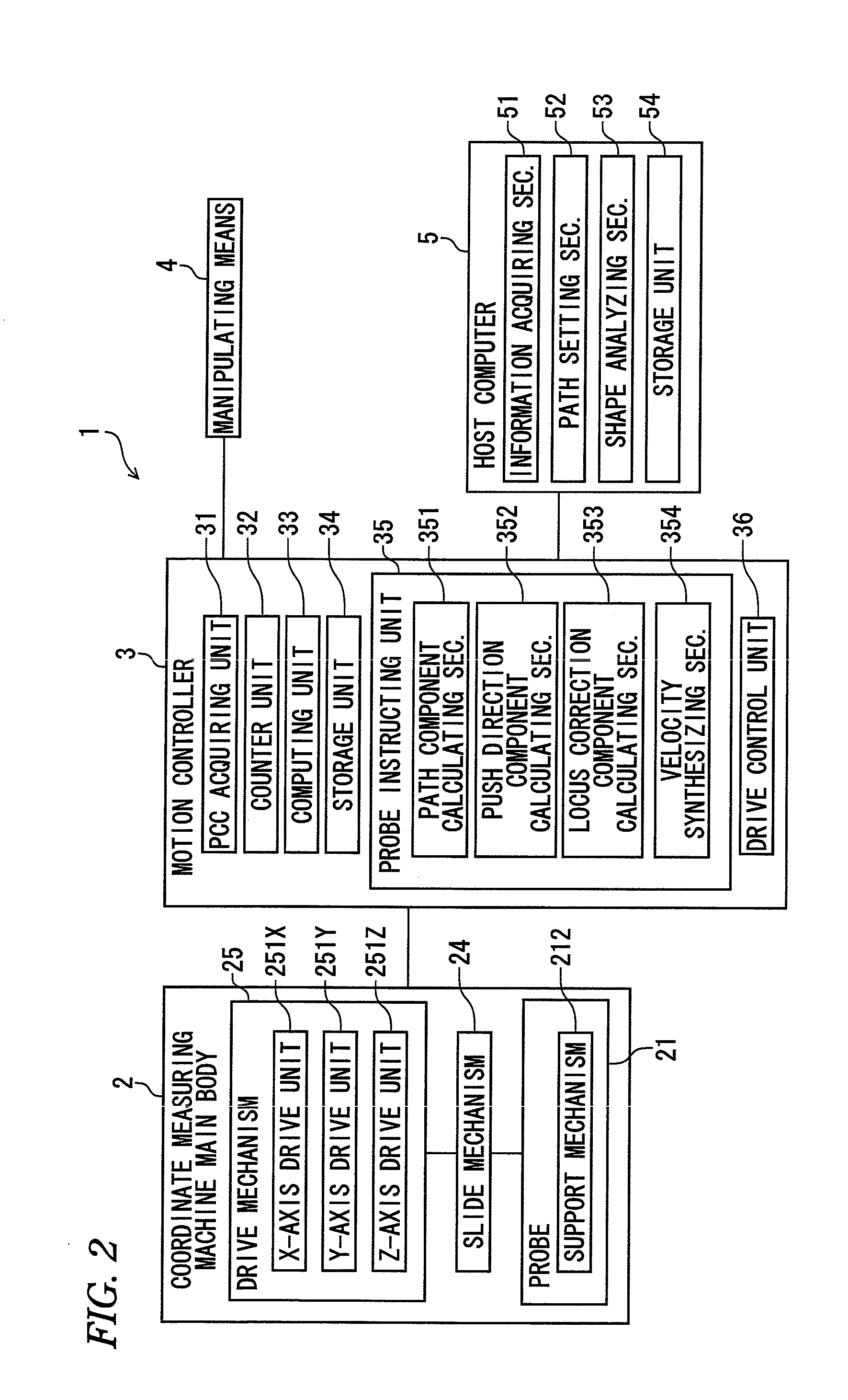
[0079]In the coordinate measuring machine 1 according to the embodiment, the information acquiring section 51 acquires design information from the CAD system (not shown) and the path setting section 52 sets a movement path of the probe 21 based on the acquired design information. The path component calculating section 351 calculates path velocity vectors {right arrow over (Vf)} (velocity component vectors along scanning directions) based on the thus-set path. Based on a deflection of the stylus tip 211A calculated by the computing unit 33, the push direction component calculating section 352 calculates a push correction vector {right arrow over (Ve)} to be used for returning the deflection to a preset, reference deflection. Based on a probe position PP and the set path, the locus correction component calculating section 353 calculates a locus correction vector {right arrow over (Vc)} to be used for returning the probe position PP to the path.

[0080]The velocit...


PUM


Abstract

A shape measuring apparatus includes: a probe having a stylus tip; a movable mechanism configured to move the stylus tip; an information acquiring unit configured to acquire design information of a workpiece; a path setting unit configured to set a path of the stylus tip; a path component calculating section configured to calculate a path velocity vector; a push direction component calculating section configured to detect a deflection, and calculate a push correction vector; a locus correction component calculating section configured to detect an amount and a direction of locus deviation of the probe from the path, and calculate a locus correction vector; a velocity synthesizing section configured to calculate a velocity synthesis vector by combining the path velocity vector, the push correction vector, and the locus correction vector; and a drive control unit configured to move the probe according to the velocity synthesis vector.

Description

CROSS-REFERENCE TO RELATED APPLICATION(S)[0001]This application is based upon and claims the benefit of priority from Japanese Patent Application No. 2012-113596, filed on May 17, 2012, the entire contents of which are incorporated herein by reference.BACKGROUND[0002]1. Field of the Invention[0003]The present invention relates to a shape measuring apparatus.[0004]2. Description of the Related Art[0005]Shape measuring apparatuses are known which are equipped with a probe having a stylus tip for measurement of a workpiece to be measured, a movable mechanism for moving the probe, and a control device for controlling the movable mechanism and which measure the shape of a workpiece to be measured by moving the stylus tip so that it scans the surface of the workpiece to be measured (refer to JP-A-2008-241420, for example).[0006]In the apparatus disclosed in JP-A-2008-241420, movement velocities of a probe are calculated by converting design values (NURBS (non-uniform rational B-spline) da...

Claims


Application Information

Patent Timeline
IPC IPC(8): G05B19/04
CPCG05B19/041G01B21/04G05B19/401G05B2219/37043G05B2219/37374G05B2219/37411Y02P90/02
Inventor NODA, TAKASHIDEGUCHI, HIROMI
Owner MITUTOYO CORP
Why Eureka
Try Eureka