Method and device for acoustically sensing an area

Active Publication Date: 2013-11-28
ROBERT BOSCH GMBH
View PDF4 Cites 4 Cited by
  • Summary
  • Abstract
  • Description
  • Claims
  • Application Information

AI Technical Summary

Benefits of technology

[0005]The present invention permits the detection of echo signals during the post-pulse oscillation time. Objects at a small distance to the acoustic transducer are thereby detectable. An otherwise blind area in close proximity to the acoustic transducer is thus able to be covered. Therefore, within the framework of collision-warning systems, a particular area is able to be

Problems solved by technology

No. 10 2004 020426 mentions the dead time, which results owing to the post-pulse oscillation, as a problem which limits a minimal measuring distance downwards.
However, the ov

Method used


Image

  • Method and device for acoustically sensing an area
  • Method and device for acoustically sensing an area
  • Method and device for acoustically sensing an area

Examples


Embodiment Construction

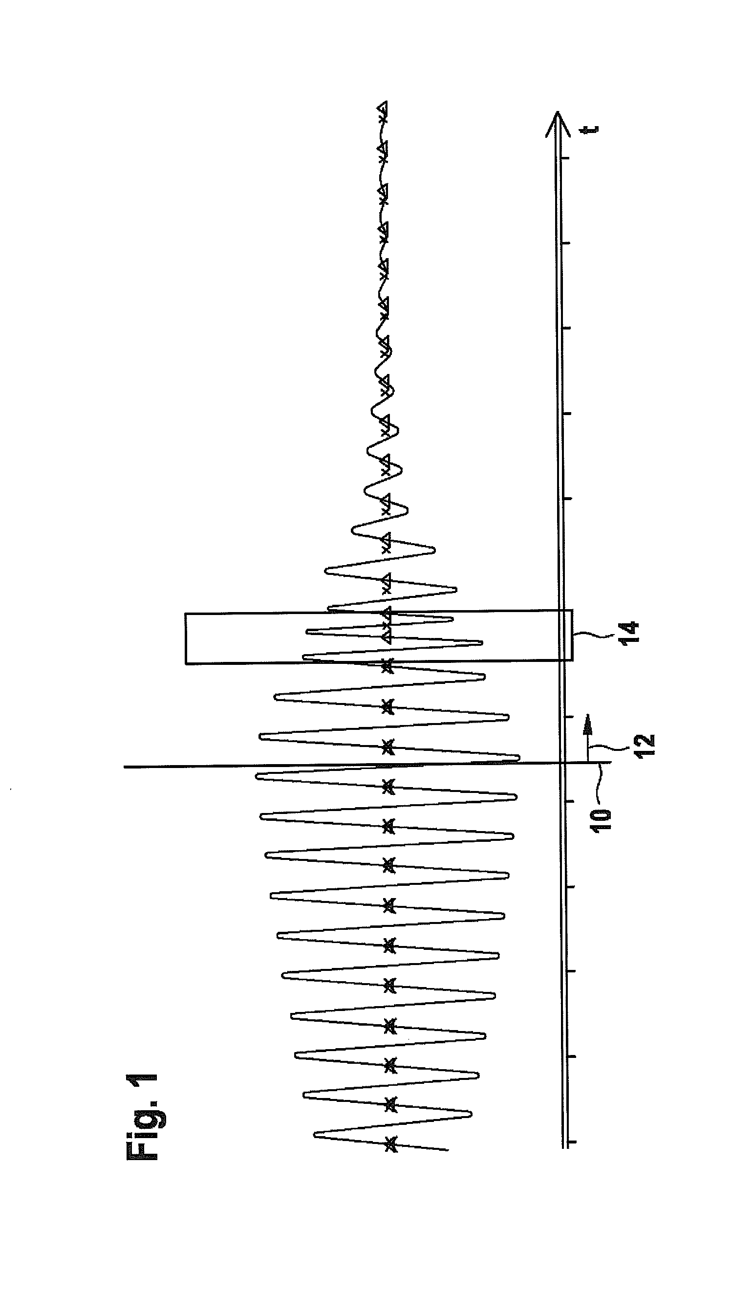
[0035]FIG. 1 shows an actual signal characteristic of a transducer, which is used according to the invention. The transducer is excited up to an instant 10, so that an increasing amplitude of oscillation results up to instant 10. Post-pulse oscillation time 12 begins as of instant 10, instant 10 representing the end of the excitation of the transducer. It is apparent that in post-pulse oscillation time 12, the signal strength decreases continuously according to the post-pulse oscillation behavior of the transducer. During time span 14, a reflected transmit pulse strikes the transducer, so that the reflected transmit pulse influences the post-pulse oscillation behavior. After time span 14 within post-pulse oscillation time 12, the reflected transmit pulse has ended, and the post-pulse oscillation behavior is no longer influenced. An actual phase response results from zero crossings of the actual signal characteristic in the positive direction, the corresponding occurrence instants be...


PUM


Abstract

A method for acoustically sensing an area is described. An acoustic transmit pulse is transmitted into the area by an acoustic transducer and a received signal is acquired with the aid of the transducer, in order to receive the transmit pulse reflected back from the area. Within a post-pulse oscillation time of the transducer, which directly follows the emission of the transmit pulse, the actual phase response of the received signal is determined. In the event the actual phase response deviates from a predefined setpoint phase response, an object is detected within the area. Also described is a device for acoustically sensing an area, which is designed to carry out the method.

Description

BACKGROUND INFORMATION[0001]It is particularly well-known from the automotive sector to use pulse-echo methods to sense the driving environment. For example, in the case of parking-assistance systems, ultrasonic transducers are used which emit a scanning pulse and receive it again. The distance between the transducer and the reflecting object is obtained from the echo time. The mass and the springiness of an acoustic transducer first of all define a self-resonant frequency of the transducer, and secondly, form mechanical energy stores. An oscillatory system results which oscillates post-pulse even after the excitation has ended. The receiving cycle begins after this post-pulse oscillation process has ended. Thus, the post-pulse oscillation defines a dead time during which no receiving is carried out, that is honored when switching over from the transmit mode to the receive mode of the transducer.[0002]For example, German Published Patent Appin. No. 10 2004 020426 mentions the dead t...

Claims


Application Information

Patent Timeline
IPC IPC(8): G01S15/93G01S15/931
CPCG01S7/527G01S2015/935G01S15/931
Inventor KALBHENN, MICHAKLOTZ, ALBRECHTSCHIRMER, JUERGENTREPTOW, THOMASSCHMID, DIRKBANNOW, NICORAPPS, PETERKIRCHNER, TOBIASDITTRICH, THOMASSCHUMANN, MICHAEL
Owner ROBERT BOSCH GMBH
Why Eureka
Try Eureka