Ultrasonic cleaning apparatus and ultrasonic cleaning method

a cleaning apparatus and ultrasonic technology, applied in the direction of cleaning process and apparatus, cleaning chemistry apparatus and process, cleaning using liquids, etc., can solve the problems of large amplitude of ultrasonic oscillation, damage to the objects to be cleaned, and bubbles are broken, so as to suppress the damage on the substrate to be cleaned, the effect of high cleaning level and high precision

Active Publication Date: 2013-11-28
KAIJOO KK
View PDF5 Cites 13 Cited by
  • Summary
  • Abstract
  • Description
  • Claims
  • Application Information

AI Technical Summary

Benefits of technology

[0030]According to the invention, the object to be cleaned is held out so as to be positioned of the ultrasonic-irradiated region in the cleaning tank of the ultrasonic transducer, and cleaning is performed without irradiating the object to be cleaned directly with the ultrasonic wave, so that damage on the substrate to be cleaned may be suppressed.
[0031]The ultrasonic wave is applied to the surface of the cleaning solution in the proximity to the surface of the object to be cleaned to excite the capillary wave, and the particulate contamination is separated from the object to be cleaned by the acoustic pressure caused by the capillary wave, so that the cleaning at a high cleaning level may be performed with respect to the highly precise substrate and the like.
[0032]The cleaning solution is supplied so as to flow in the same direction as the direction of propagation of the capillary wave, so that re-adhesion of the particulate contamination separated from the objects to be cleaned may be prevented.
[0033]The object to be cleaned are held so as to extend in parallel to the liquid surface of the cleaning solution in the cleaning tank and be positioned in the vicinity of the liquid level of the cleaning solution, and the distance from the object to be cleaned to the liquid surface of the cleaning solution is set to be 10 mm (millimeter) or smaller, so that the depth of the cleaning tank may be small, and hence the cleaning with small amount of the cleaning solution is enabled.
[0034]Since the capillary wave propagates over the entire area of the object to be cleaned along the surface of the object to be cleaned according to the invention, there is no moving device configured to move the object to be cleaned during cleaning, so that the ultrasonic cleaning apparatus may be simplified.

Problems solved by technology

However, when an amplitude of the ultrasonic oscillations increases, the air bubbles are broken in the positive cycle, and an impact wave generated at that time causes damage to the objects to be cleaned.
In particular, in low-frequency ultrasonic waves not exceeding 100 kHz, the amplitudes of the ultrasonic oscillations are large, and hence the objects to be cleaned are subject to damage.
However, in the dip-system ultrasonic cleaning of the related art in which a plurality of the substrates are cleaned simultaneously, the cleaning solution flows along the surfaces of the objects to be cleaned, but layers of several microns or smaller flowing little or never exist along interfaces.
Therefore, there is a problem that the contamination adhered to the surfaces of the objects to be cleaned may not be removed sufficiently.
Although application of the ultrasonic waves is effective as a device for destabilizing the layer of the cleaning solution in the vicinity of the surfaces of the objects to be cleaned, there is a problem that sufficient cleaning is not achieved with an ultrasonic wave on the order of 1 MHz the amplitude of the ultrasonic oscillations of which is small.
Furthermore, in a case of a semiconductor device progressed in miniaturization, occurrence of damage is reported even with the ultrasonic wave on the order of 1 MHz the amplitude of the ultrasonic oscillations of which is small.
Therefore, the semiconductor device progressed in miniaturization may be subject to occurrence of damage by being influenced by the ultrasonic oscillations even with the ultrasonic wave on the order of 1 MHz the amplitude of the ultrasonic oscillations of which is small.

Method used


Image

  • Ultrasonic cleaning apparatus and ultrasonic cleaning method
  • Ultrasonic cleaning apparatus and ultrasonic cleaning method
  • Ultrasonic cleaning apparatus and ultrasonic cleaning method

Examples


first embodiment

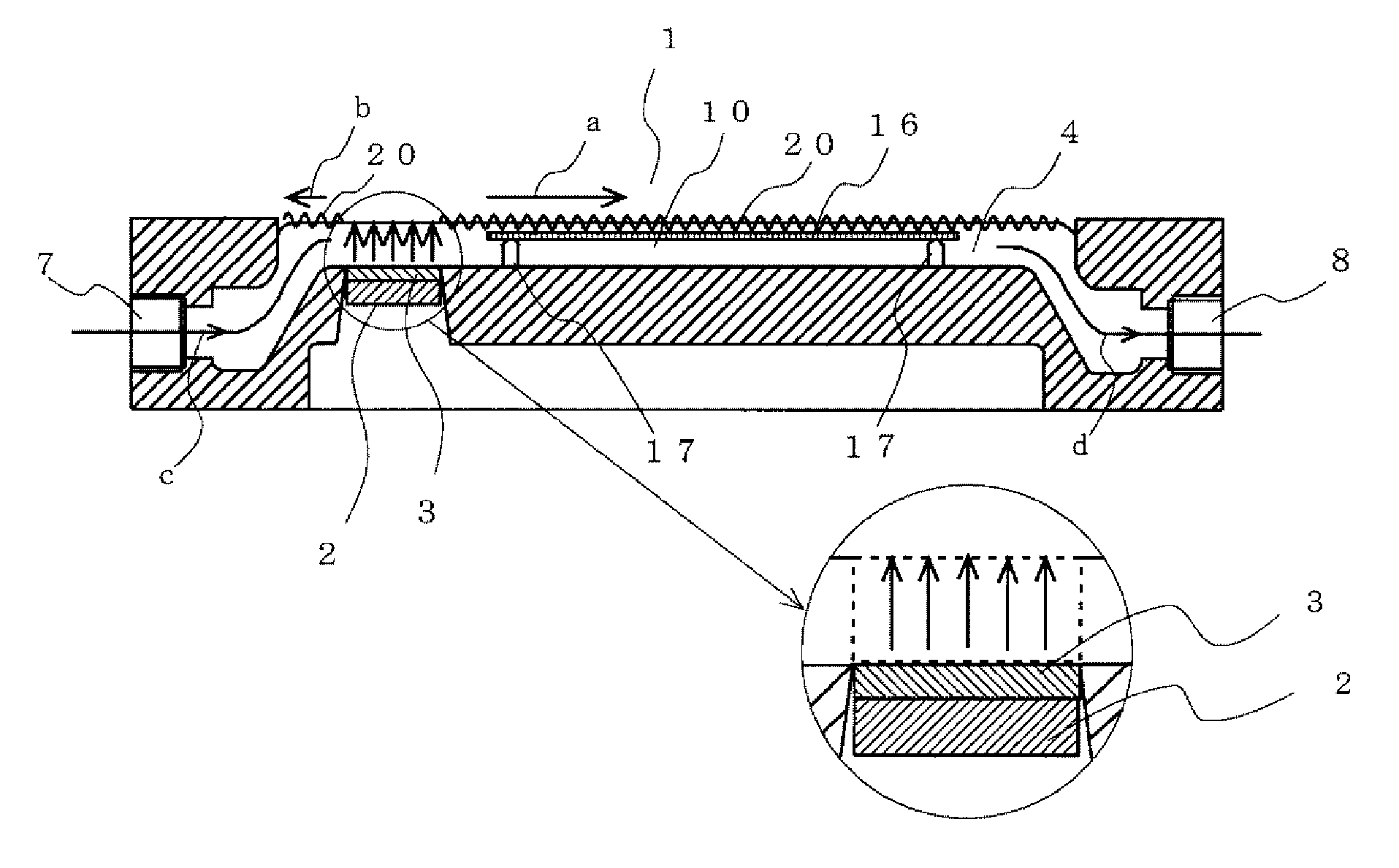
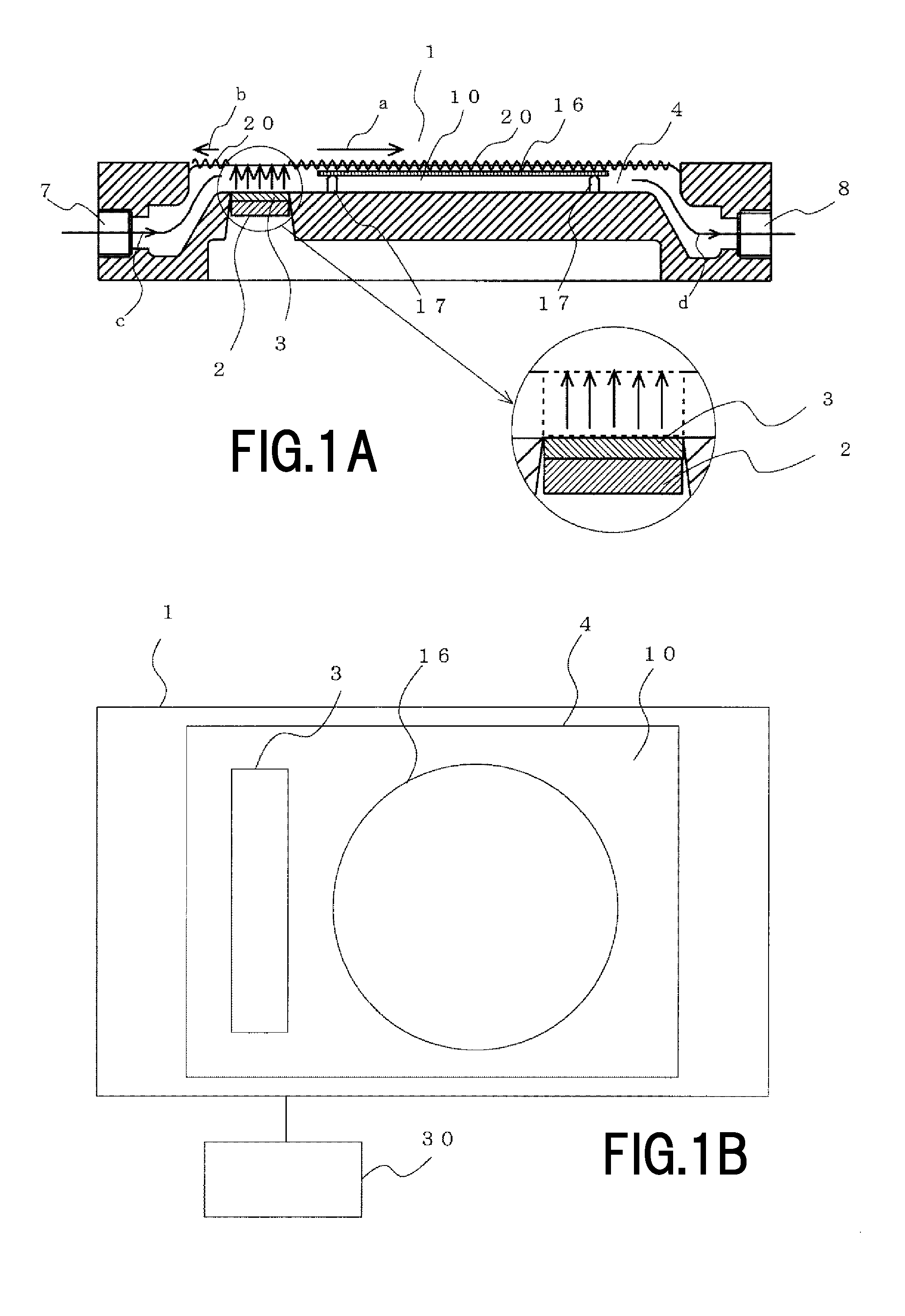
[0062]FIG. 1A is a partly enlarged cross-sectional front view illustrating a configuration of an ultrasonic cleaning apparatus according to a first embodiment of the invention;

[0063]FIG. 1B is a plan view illustrating the configuration of the ultrasonic cleaning apparatus. The ultrasonic cleaning apparatus illustrated in FIGS. 1A and 1B are of a single wafer system that processes silicon wafers one by one. As illustrated in FIGS. 1A and 1B, an ultrasonic cleaning apparatus 1 includes a cleaning tank 4 configured to store a cleaning solution 10, a cleaning solution supply port 7 (illustrated in FIG. 1A) provided on a side surface of the cleaning tank 4, a cleaning liquid draining port 8 (illustrated in FIG. 1A) provided on a side surface facing the side surface of the cleaning tank 4 having the cleaning solution supply port 7, a vibrating plate 3 provided on a bottom of the cleaning tank 4 on the side of the cleaning solution supply port 7, an ultrasonic transducer 2 provided on a lo...

second embodiment

[0104]Subsequently, an ultrasonic cleaning apparatus according to a second embodiment in which cleaning is performed while moving the object to be cleaned will be described. FIG. 15 is a cross-sectional view illustrating a configuration of the ultrasonic cleaning apparatus according to the second embodiment of the invention. The ultrasonic cleaning apparatus 1 illustrated in FIG. 1 and FIG. 3 performs cleaning of the object to be cleaned 16 in the state of being immersed in the cleaning tank 4 and fixed. In contrast, an ultrasonic cleaning apparatus 33 illustrated in FIG. 15 is configured to perform cleaning while moving the object to be cleaned 16. The same components as those in FIG. 1 are denoted by the same reference numerals, and detailed descriptions relating to the configuration thereof are omitted.

[0105]As illustrated in FIG. 15, the ultrasonic cleaning apparatus 33 includes a cleaning tank 36 configured to store the cleaning solution 10, a storage portion 34 configured to s...


PUM


Abstract

There are provided an ultrasonic cleaning apparatus and an ultrasonic cleaning method capable of suppressing occurrence of damage on a substrate to be cleaned and capable of performing cleaning at a high cleaning level for highly precise substrates and the like used in an electronics industry. Occurrence of damage on the substrate to be cleaned is suppressed by holding an object to be cleaned so as to be positioned out of a region where perpendiculars extend from an oscillating surface of an ultrasonic transducer to a liquid surface (an ultrasonic-irradiated region) under and in the vicinity of the liquid surface of a cleaning solution, exciting a capillary wave on a surface of the cleaning solution by an ultrasonic wave, and separating particulate contamination of the object to be cleaned by an acoustic pressure generated by the capillary wave without irradiating the object to be cleaned directly with the ultrasonic wave.

Description

BACKGROUND OF THE INVENTION[0001]1. Field of the Invention[0002]The present invention relates to an ultrasonic cleaning apparatus and an ultrasonic cleaning method and, more specifically, to an ultrasonic cleaning apparatus and an ultrasonic cleaning method capable of cleaning at a high cleaning level without causing damage to objects to be cleaned.[0003]2. Description of the Related Art[0004]In an electronics industry, high cleaning levels are required in cleaning of glass substrates or substrates for silicon wafers. Examples of methods of cleaning objects to be cleaned such as the substrates as described above include a dip system in which a plurality of the substrates are immersed in a cleaning solution and a single wafer system in which the cleaning solution is injected onto the substrates and clean the same one by one. In recent years, the single wafer system which allows the cleaning at the high cleaning levels and is advantageous in terms of costs is predominantly employed. T...

Claims


Application Information

Patent Timeline
Patent Type & Authority Applications(United States)
IPC IPC(8): B08B3/12H01L21/67
CPCB08B3/12H01L21/67057H01L21/02052H01L21/02057H01L21/302
Inventor SUZUKI, KAZUNARI
Owner KAIJOO KK
Why Eureka
Try Eureka