

Tire cord fabric and pneumatic tire
- Summary
- Abstract
- Description
- Claims
- Application Information
AI Technical Summary
Benefits of technology
Problems solved by technology
Method used
Image

Examples
working examples
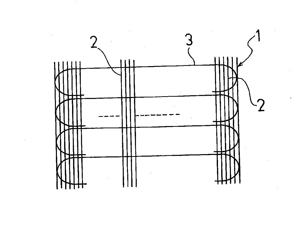
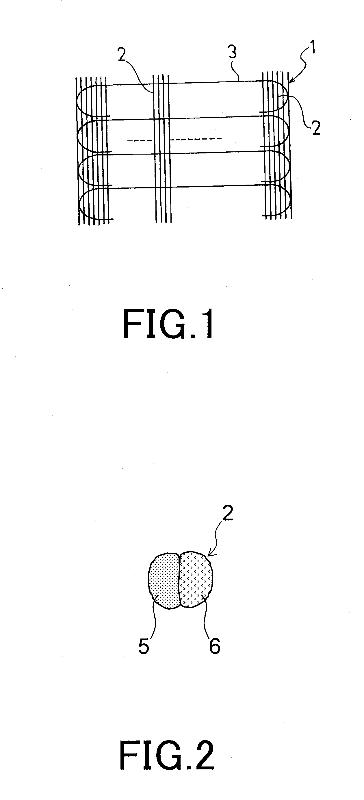
[0056]13 types of tire cord fabric were fabricated as tire cord fabric to be used in the belt cover layer of a pneumatic tire. Conventional examples 1 to 4 and working examples 1 to 9 as indicated in Tables 1 and 2 were varied in the thickness and material of the first twist yarns 1 and 2 that configure the warp yarn, the twist direction of the twist yarns in the warp yarn, the total fiber fineness D1 of the warp yarn, and the material, the cord construction, the elongation at break, and the yarn fiber fineness D2 of the weft yarn, and the ratio D1 / D2 between the total fiber fineness D1 of the warp yarn and the yarn fiber fineness D2 of the weft yarn. The first twist yarn 1 is the aramid first twist yarn and the first twist yarn 2 is the aliphatic polyamide first twist yarn. The number after the “x” symbol in the first twist yarn thickness column indicates the number of strands of the first twist yarn. “Z” indicates the first twist direction and “S” indicates the second twist direct...
PUM
| Property | Measurement | Unit |
|---|---|---|
| Fraction | aaaaa | aaaaa |
| Fraction | aaaaa | aaaaa |
| Elongation at break | aaaaa | aaaaa |
Abstract
Description
Claims
Application Information