Vibration limit switch system

Active Publication Date: 2013-11-28
VEGA GRIESHABER GMBH & CO
View PDF6 Cites 8 Cited by
  • Summary
  • Abstract
  • Description
  • Claims
  • Application Information

AI Technical Summary

Benefits of technology

[0014]The proposed invention provides a vibration limit switch system with a piezoelectric transmitting- and/or receiving unit, in operable connection with a membrane that can be put in oscillation, and a mechanical oscillation arrangement that is coupled to the membrane, whereby the piezoelectric transmitting- and/or receiving unit is adhered directly, or via an adapt

Problems solved by technology

It is well recognized in the vibration limit switches known from the prior art and with the design described above, as a strong disadvantage that tears fre

Method used


Image

  • Vibration limit switch system
  • Vibration limit switch system
  • Vibration limit switch system

Examples


Embodiment Construction

[0054]Reference will now be made in detail to several embodiments of the invention that are illustrated in the accompanying drawings. Wherever possible, same or similar reference numerals are used in the drawings and the description to refer to the same or like parts or steps. The drawings are in simplified form and are not to precise scale. For purposes of convenience and clarity only, directional terms, such as top, bottom, up, down, over, above, and below may be used with respect to the drawings. These and similar directional terms should not be construed to limit the scope of the invention in any manner. The words “connect,”“couple,” and similar terms with their inflectional morphemes do not necessarily denote direct and immediate connections, but also include connections through mediate elements or devices.

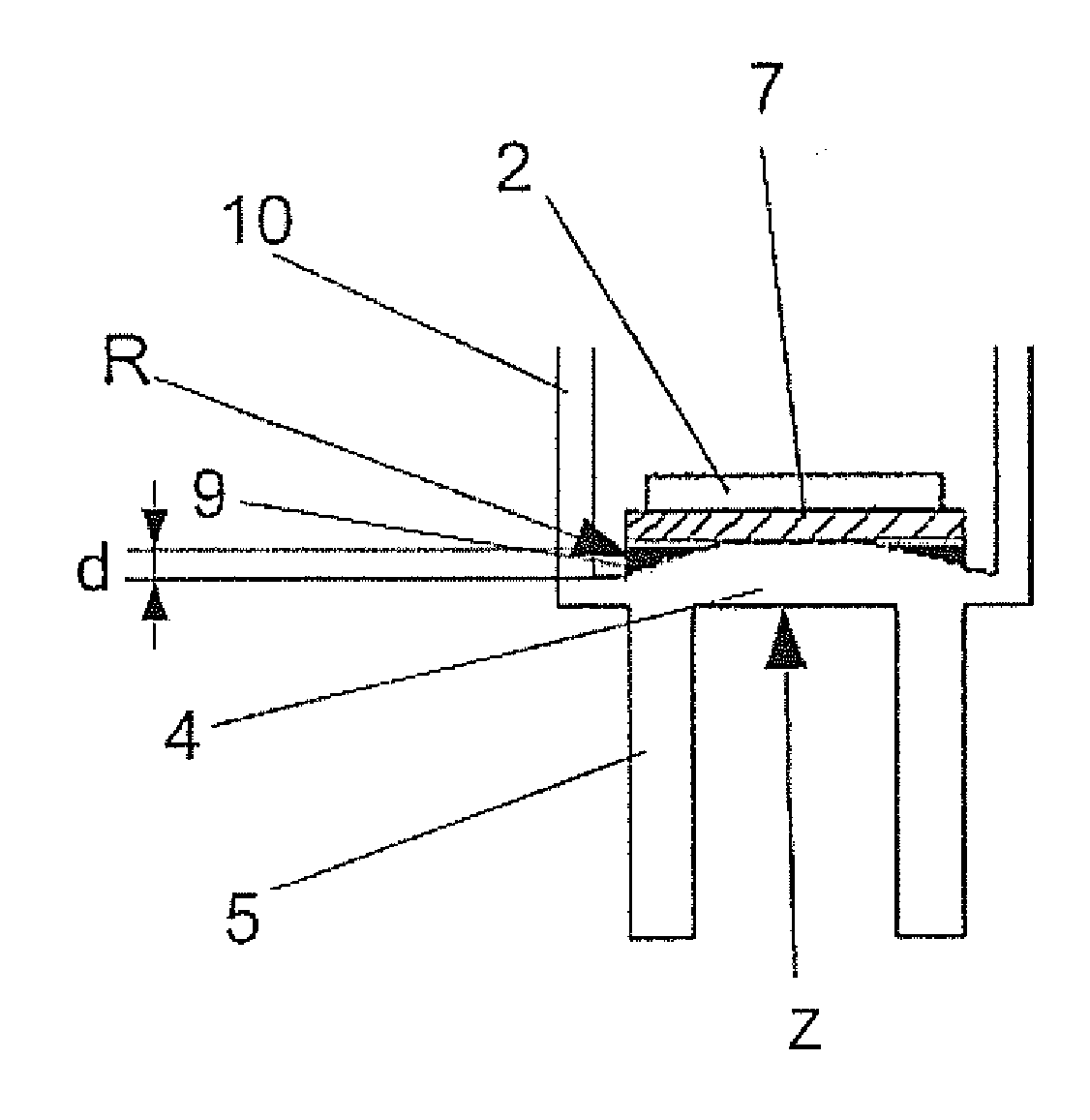
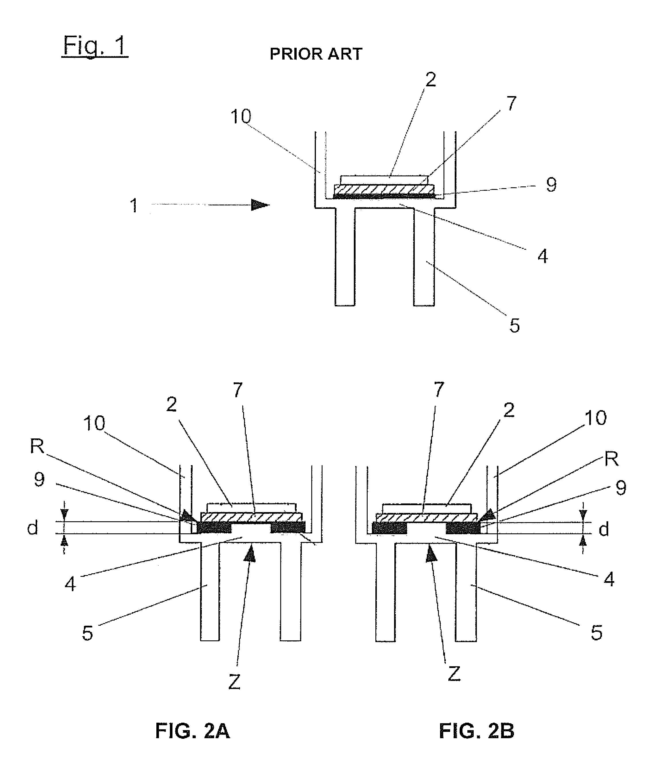
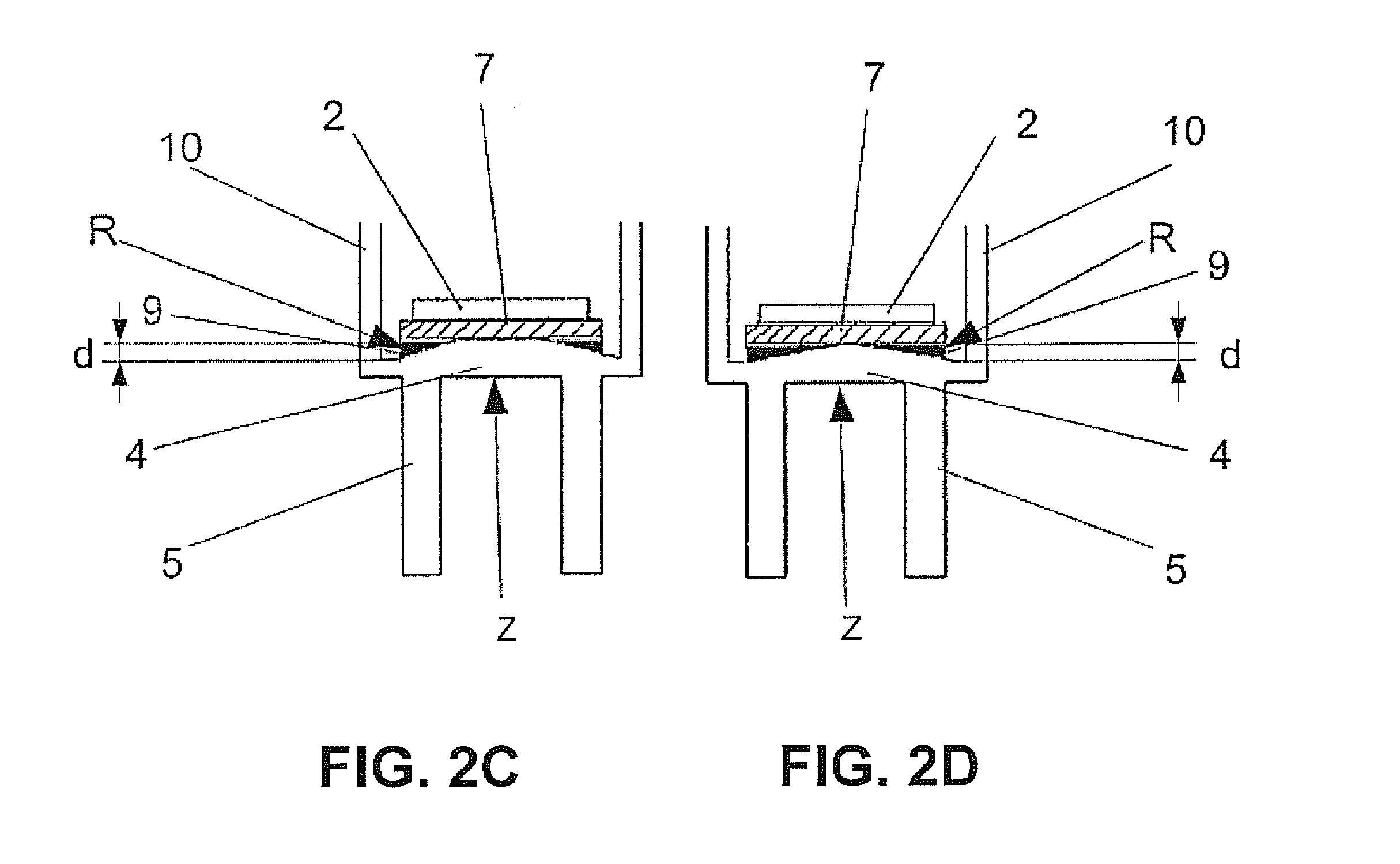
[0055]Referring now to FIGS. 2A-2D overall which show four preferred and non-limiting exemplary embodiments of the proposed invention for a vibration limit switch system in a...


PUM

PropertyMeasurementUnit
Thicknessaaaaaaaaaa
Shapeaaaaaaaaaa
Areaaaaaaaaaaa

Abstract

A vibration limit switch system and related method is provided with a piezoelectric transmitting- and/or receiving unit, in operable connection with a membrane that can be put in oscillation, and a mechanical oscillation arrangement that is coupled to the membrane, whereby the piezoelectric transmitting- and/or receiving unit is adhered directly, or via an adaptation layer by an adhesive layer, to the membrane 4. In this improvement, the adhesive layer between the membrane and the transmitting-and/or receiving unit or the adaptation layer has a thickness in an edge area R which thickness is elevated in comparison to a central area Z. This thickness is arranged in differing geometries and amounts to further improve performance.

Description

CROSS REFERENCE TO RELATED APPLICATIONS[0001]This application relates to, and claims priority from, EP Ser. No. 11 188 443.3 filed Nov. 9, 2011, and from U.S. Ser. No. 61 / 562,023 filed Nov. 21, 2011, the entire contents of each of which are fully incorporated herein by reference.FIGURE SELECTED FOR PUBLICATION[0002]FIG. 2ABACKGROUND OF THE INVENTION[0003]1. Field of the Invention[0004]The present invention relates to a vibration limit switch system. More particularly, the present invention relates to vibration limit switch system that eliminates thermally and other induced shearing forces.[0005]2. Description of the Related Art[0006]The detection of the limiting status plays an important part in industrial processes, in particular for liquids and bulk materials. In the determination of the limiting status the attaining of a defined filling height is detected and converted into a switching command. The switching command then starts or stops, for example, a filling apparatus so that a...

Claims


Application Information

Patent Timeline
IPC IPC(8): H01H3/16H01H11/00
CPCH01H3/16H01H11/00G01F23/2967Y10T29/42
Inventor MELLERT, MARTINJACOB, JOERNGRUHLER, HOLGER
Owner VEGA GRIESHABER GMBH & CO
Why Eureka
Try Eureka