Tie Rod Lock

a technology of tie rods and locking rods, which is applied in the direction of mechanical equipment, transportation and packaging, and machining, etc., can solve the problems of complete loss of control of the horizontal stabilizer, and achieve the effect of increasing leverage and control

Active Publication Date: 2013-11-28
PARKER INTANGIBLES LLC
View PDF9 Cites 22 Cited by
  • Summary
  • Abstract
  • Description
  • Claims
  • Application Information

AI Technical Summary

Benefits of technology

[0007]This secondary load path enables locking of the attached stabilizer in a fixed position with minimized backlash. This avoids erratic movement of the stabilizer and hence permits the pilot to regain control through other mechanisms whereby the continued flight and landing of the aircraft can be more readily controlled. Thus the locking operation of the secondary load path shall be clearly detected by the pilot or operator during the flight by shutting down the drive system and holding the horizontal stabilizer in a fixed position. Steps can then be taken to repair or replace the stabilizer actuator prior to the next flight.
[0010]2) the ability of the locking mechanism for the secondary load path to achieve permanent, fixed immobilization under minimal aerodynamic triggering loads;
[0011]3) the ability of the locking mechanism to keep the stabilizer actuator immobilized even though aerodynamic loads of varying magnitudes are applied to the stabilizer up to the tensile and compressive design load limits;
[0024]Optionally, the lock housing further includes one or more radial ports adjacent to the protrusion thereby allowing access to reset the locking mechanism from the failsafe position to the standby position.
[0027]Optionally, the stabilizer actuator further includes at least one protrusion having at least one inwardly extending circumferential rib and wherein the segment comprises a latch segment having an outwardly extending circumferential flange configured to prevent relative axial movement between the tie rod and the lock housing by interacting with the at least one rib, and wherein the at least one protrusion comprises an axial slot through the at least one rib forming at least one inwardly extending axial ridge and wherein the at least one segment comprises a lock segment having an outward extending axial flange configured to prevent relative radial movement between the tie rod and the lock housing by interacting with the at least one ridge.
[0030]Optionally the inserting includes threading the tool into the lock housing for increased leverage and control.

Problems solved by technology

Failures of the primary load path such as caused by fracture and separation of the ballscrew shaft or ballscrew flange or failure of a primary load path attachment can result in the complete loss of control of the horizontal stabilizer.

Method used


Image

  • Tie Rod Lock
  • Tie Rod Lock
  • Tie Rod Lock

Examples


Embodiment Construction

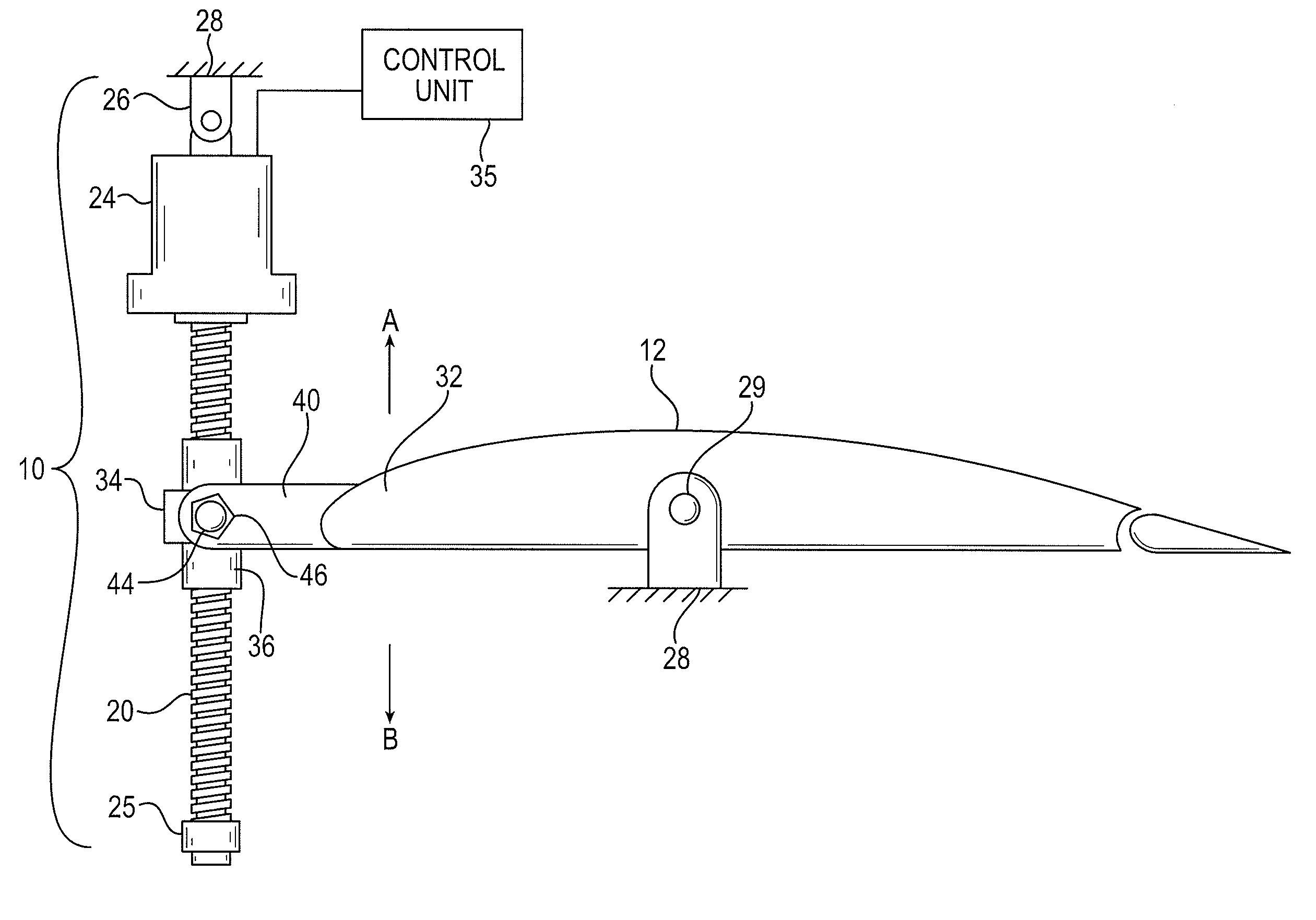
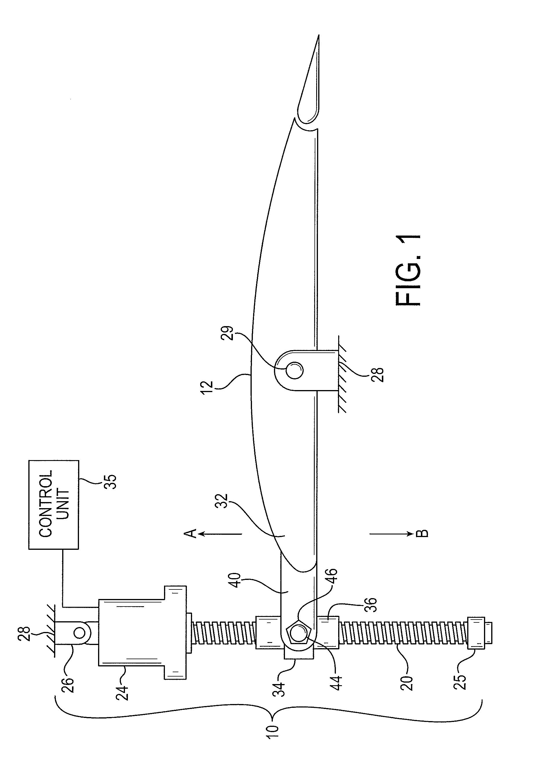
[0068]Looking now to FIG. 1, a representative stabilizer actuator 10 is shown for selectively controlling the position of a horizontal stabilizer 12. Although the actuator 10 is shown in a vertical orientation, the orientation of exemplary actuators may be different, and in particular embodiments is reversed from that which is shown in FIG. 1. The actuator 10 a primary ball nut assembly 36 connected by threads with a ballscrew 20. The ballscrew 20 may extend generally vertically and may be connected at its upper (or lower) end to a hydraulic or electric drive motor and gear assembly 24. An end cap 25 is fixed to the opposite lower (or upper) end of the ball screw 20 to assure that the ballscrew 20 will not be unthreaded from the primary ball nut assembly 36. The drive motor and gear assembly 24 is connected to an upper (or lower) support gimbal 26 which in turn is pivotally secured at a fixed position to a portion of the rudder section or tail section 28 of the fuselage. The drive m...


PUM


Abstract

A stabilizer actuator has a first end for connecting to an aircraft support structure and a second end for connecting to a stabilizer. The actuator includes a primary load path for transmittal of loads acting on the stabilizer to the aircraft support structure, and a secondary load path for transmittal of loads acting on the stabilizer to the aircraft support structure upon failure of the primary load path. The secondary load path includes a tie rod extending along a longitudinal axis, a load path locking mechanism coupled to the tie rod, a lock housing having a central bore for receiving the locking mechanism, and at least one radially movable segment that, upon failure of the primary load path, moves radially to lock the tie rod to the lock housing against axial and / or radial movement.

Description

RELATED APPLICATIONS[0001]This application claims the benefit of U.S. Provisional Application No. 61 / 559,960 filed Nov. 15, 2011, which is hereby incorporated herein by reference.FIELD OF INVENTION[0002]The present invention relates generally to aircraft actuators, and more particularly to engaging a secondary load path in a horizontal stabilizer trim actuator of an aircraft.BACKGROUND[0003]Aircraft typically include a plurality of flight control surfaces that, when controllably positioned, guide the movement of the aircraft from one destination to another. The number and type of flight control surfaces included in an aircraft may vary, but typically include both primary flight control surfaces and secondary flight control surfaces. The primary flight control surfaces are those that are used to control aircraft movement in the pitch, yaw, and roll axes, and the secondary flight control surfaces are those that are used to influence the lift or drag (or both) of the aircraft. Although...

Claims


Application Information

Patent Timeline
Patent Type & Authority Applications(United States)
IPC IPC(8): B64C13/28F16H25/22
CPCB64C13/28F16H25/2204B64C13/341B64C5/16Y10T74/18576
Inventor HALE, BRIAN CURTIS
Owner PARKER INTANGIBLES LLC
Why Eureka
Try Eureka