Amorphous stator, and electric motor using same

Active Publication Date: 2013-11-28
AMOTECH
View PDF13 Cites 15 Cited by
  • Summary
  • Abstract
  • Description
  • Claims
  • Application Information

AI Technical Summary

Benefits of technology

[0026]As described above, the present invention provides an amorphous stator for use in a high-power, high-speed electric motor, and an electric motor using the amorphous stator, in which amorphous alloy powder is compressed and molded into unit split cores, to thus assemble the unit split cores by using bobbins, instead of coupling the unit split cores mutually directly, and to thereby design a shape of the unit split cores into a simple structure of easy compression molding, and easily achieve core-molding.
[0027]In addition, the present invention provides an amorphous magnetic component for use in a high-power, high-speed electric motor, and an electric motor using the amorphous stator, in which a mixture of plate-shaped amorphous alloy powder and spherical soft magnetic powder is molded into unit split cores, to thus promote improved permeability and improved packing density, and a core loss is minimized, to thus promote improvement of an efficiency of the motor.
[0028]In addition, the present invention provides a high-power, high-speed electric motor having the number of poles that operate in a frequency band of at least 10 kHz or higher so that permeability properties of amorphous alloy materials

Problems solved by technology

The slotted stators cause difficult windings, require a lot of time on winding operations, and require complex and expensive coil winding equipment.
Also, a structure formed of a number of teeth induces a magnetic discontinuity, to thus affect the efficiency of a motor, and generate a cogging torque depending on the presence of slots.
In the case of a material such as an electric steel plate, the thickness of the electric steel plate is thick, to accordingly increase an iron loss, and exhibit the low efficiency in high-speed motors.
In conventional Si—Fe-based materials, a loss caused by a changing magnetic field at a frequency of about 400 Hz or more may heat the Si—Fe-based materials until the materials cannot be often cooled by even any suitable cooling devices.
Until now, it has been known that it is very difficult to provide electric devices that are easily manufactured while taking the advantages of low-loss materials, at a low-cost.
Most of attempts of applying the low-loss materials in the conventional devices have failed.
These electric devices show improved efficiency with low losses, from time to time, but may raise problems of causing a severe deterioration of the output, and big costs related to the handling such as molding of amorphous metal.
When compared with the non-oriented electric steel plates, an amorphous metal provides excellent magnetic performance, but has been considered for a long time that it is unsuitable to be used as a bulk magnetic member such as a rotor or stator for electric motors, because of certain physical properties and obstacles that occur at the time of fabrication.
For example, the amorphous metal is thinner and lighter than the non-oriented electric steel plate, and thus a fabrication tool and die will wear more rapidly.
When compared with the conventional technology such as punching or stamping, fabrication of the bulk amorphous metal magnetic member has no commercialized competitiveness due to an increase in fabrication costs for the tools and dies.
Thin amorphous metal also leads to an increase in the number of the laminates in the assembled member, and also increases the overall cost of the amorphous metal rotor or stator magnet

Method used


Image

  • Amorphous stator, and electric motor using same
  • Amorphous stator, and electric motor using same
  • Amorphous stator, and electric motor using same

Examples


Example

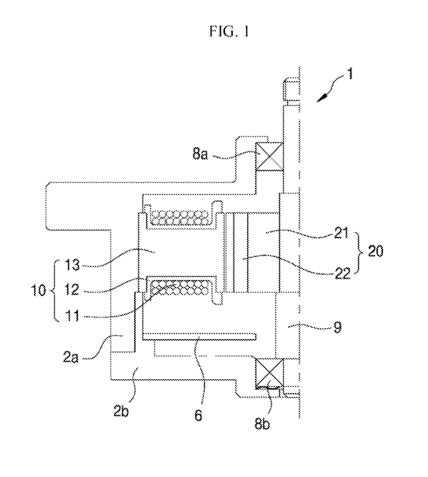
[0058]A motor 1 shown in FIG. 1, according to a first embodiment of the present invention, illustrates an application where the motor is applied to a driving motor for an air absorbing device of a vacuum cleaner, in which including a core of a stator and a back yoke of a rotor in which an integral core stator and an interior permanent magnet (IPM) type rotor are combined with each other in the motor, and in which the core of the stator and the back yoke of the rotor are all molded with amorphous alloy powder.

[0059]First, the entire motor will be descried below. In the motor 1, first and second bearings 8a and 8b are provided at a housing 2a and a lower cover 2b, respectively, and an upper side of the lower cover 2b is combined with an inner circumferential portion of the housing 2a. Accordingly, a stator 10 is fixedly provided. Here, a rotor 20 is arranged in a space formed at the central portion of the stator 10, and a rotating shaft 9 combined at the central portion of the rotor 2...

Example

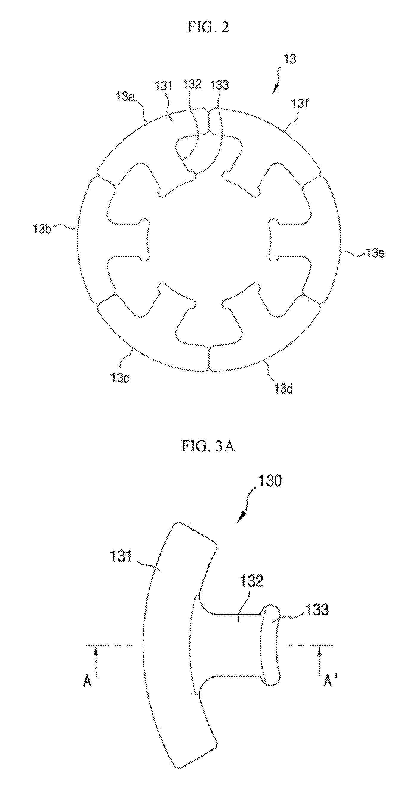
[0104]Hereinbelow, a split core type stator according to a second embodiment of the present invention will be described with reference to FIGS. 7A to 8B.

[0105]FIGS. 7A and 7B are a schematic plan view and a front view showing a structure where a split type bobbin is combined on a split core type stator core according to a second embodiment of the present invention, respectively. FIGS. 8A and 8B are a plan view and a front view enlarging and showing one of split cores shown in FIG. 7A, respectively.

[0106]A split core type stator according to a second embodiment of the present invention is implemented by using a number of unit split cores 13a-13f (or 130) shown in FIGS. 2 to 3B, so as to be used in combination with a single rotor, similarly to the first embodiment.

[0107]The stator 10 of the first embodiment is implemented by combining a number of unit split cores 13a-13f (or 130) in an annular form by using integral bobbins 12a and 12b, but the split core type stator 10a according to ...

Example

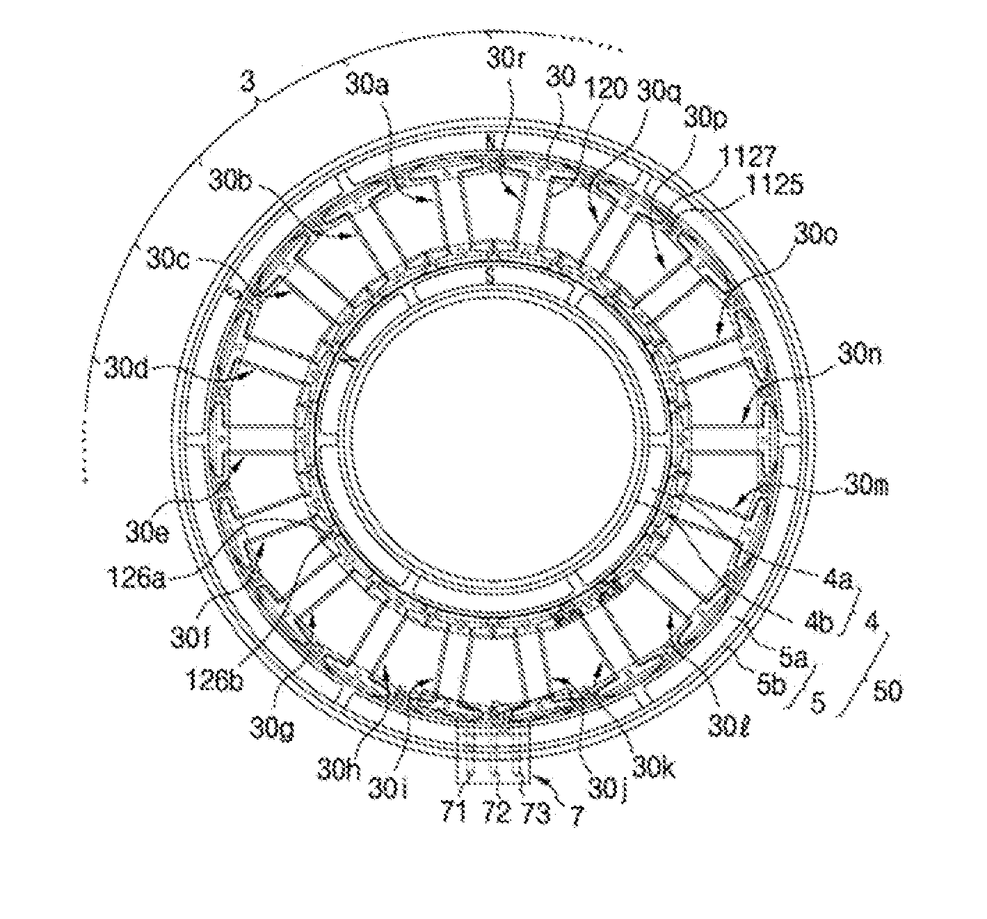
[0122]A BLDC (brushless direct-current) motor according to the third embodiment can be implemented into a 6-pole and 18-slot structure as shown in FIG. 9, in the case that the BLDC motor is applied for the drive devices in the washing machines. In this case, the inner rotor 4 and the outer rotor 5 are attached to the inner surface and outer surface of the inner and outer yokes 4b and 5b in which 6-pole magnets 4a and 5a where three N-poles and three S-poles are alternately arranged are place in an annular form, respectively, and the magnets facing each other in the inner rotor 4 and the outer rotor 5 are preferably placed to have the opposite polarity.

[0123]An annular stator 3 including eighteen (18) unit split cores 30 has been inserted into an annular space between the double rotor 50 having the inner rotor 4 and the outer rotor 5. The annular stator 3 may be integrated by insert molding with a resin or fixed by using a support bracket 40 combined with the bobbin 20.

[0124]The stat...


PUM


Abstract

Provided is an amorphous stator for use in a high-power, high-speed electric motor, and an electric motor using the amorphous stator, in which amorphous alloy powder is compressed and molded into a number of unit split cores, to then be assembled with bobbins, and to thus be easily molded into a core of a complex shape, and a core loss is minimized by using the amorphous alloy powder, to thus promote improvement of an efficiency of the motor. The electric motor includes: a stator in which a coil is wound on bobbins respectively formed in a number of unit split cores, and the number of unit split cores are assembled in an annular form by an integral or split bobbin; and a rotor that is rotated by an interaction with the stator, wherein the unit split cores are molded with mixed powder made of plate-shaped amorphous alloy powder and spherical soft magnetic powder.

Description

TECHNICAL FIELD[0001]The present invention relates to an amorphous stator and an electric motor using the amorphous stator, and more specifically, to an amorphous stator for use in a high-power, high-speed electric motor, and an electric motor using the amorphous stator, in which amorphous alloy powder is compressed and molded into a number of unit split cores, to then be assembled with bobbins, and to thus be easily molded into a core of a complex shape, and a core loss is minimized by using the amorphous alloy powder, to thus promote improvement of an efficiency of the motor.BACKGROUND ART[0002]The slotted stators cause difficult windings, require a lot of time on winding operations, and require complex and expensive coil winding equipment. Also, a structure formed of a number of teeth induces a magnetic discontinuity, to thus affect the efficiency of a motor, and generate a cogging torque depending on the presence of slots. In the case of a material such as an electric steel plat...

Claims


Application Information

Patent Timeline
IPC IPC(8): H02K1/12
CPCH02K1/12H02K1/02H02K1/148H02K1/185H02K1/187H02K21/12H02K2213/03H02K15/02H02K3/522
Inventor KIM, BYOUNG SOO
Owner AMOTECH
Why Eureka
Try Eureka