Antenna apparatus including two pairs of antennas provided respectively to be symmetric with respect to symmetric line
a technology of antenna apparatus and antenna, which is applied in the direction of antenna details, elongated active element feed, antennas, etc., can solve the problems of reducing the signal-to-noise ratio at the time of receiving by using the antenna, the inability of the antenna to help being arranged in the vicinity, and the inability to achieve the effect of preventing the loss of gain
- Summary
- Abstract
- Description
- Claims
- Application Information
AI Technical Summary
Benefits of technology
Problems solved by technology
Method used
Image

Examples
modified embodiment of first embodiment
[0091]FIG. 17 is a plan view showing an antenna apparatus according to a modified embodiment of the first embodiment of the present disclosure. FIG. 18 is a plan view of the antenna 2A of FIG. 17, and FIG. 19 is a plan view of the antenna 3A of FIG. 17. Moreover, in FIGS. 17, 18 and 19, the same components as those of FIGS. 2, 4 and 5 are denoted by same reference numerals, and no description is provided therefor. In FIG. 17, the rightward direction is referred to as an X-axis direction, and the upward direction is referred to as a Y-axis direction. Further, a direction opposite to the X-axis direction is referred to as a −X-axis direction, and a direction opposite to the Y-axis direction is referred to as a −Y1-axis direction. Referring to FIG. 17, the antenna apparatus of the present modified embodiment differs from the antenna apparatus (see FIG. 2) of the first embodiment in that antennas 1A, 2A, 3A and 4A are provided in place of the antennas 1, 2, 3 and 4. Only the points of d...
second embodiment
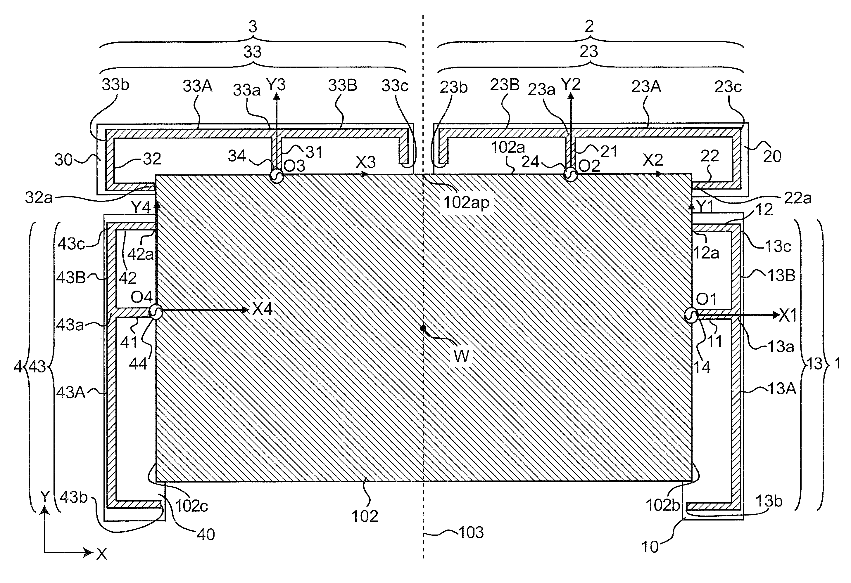
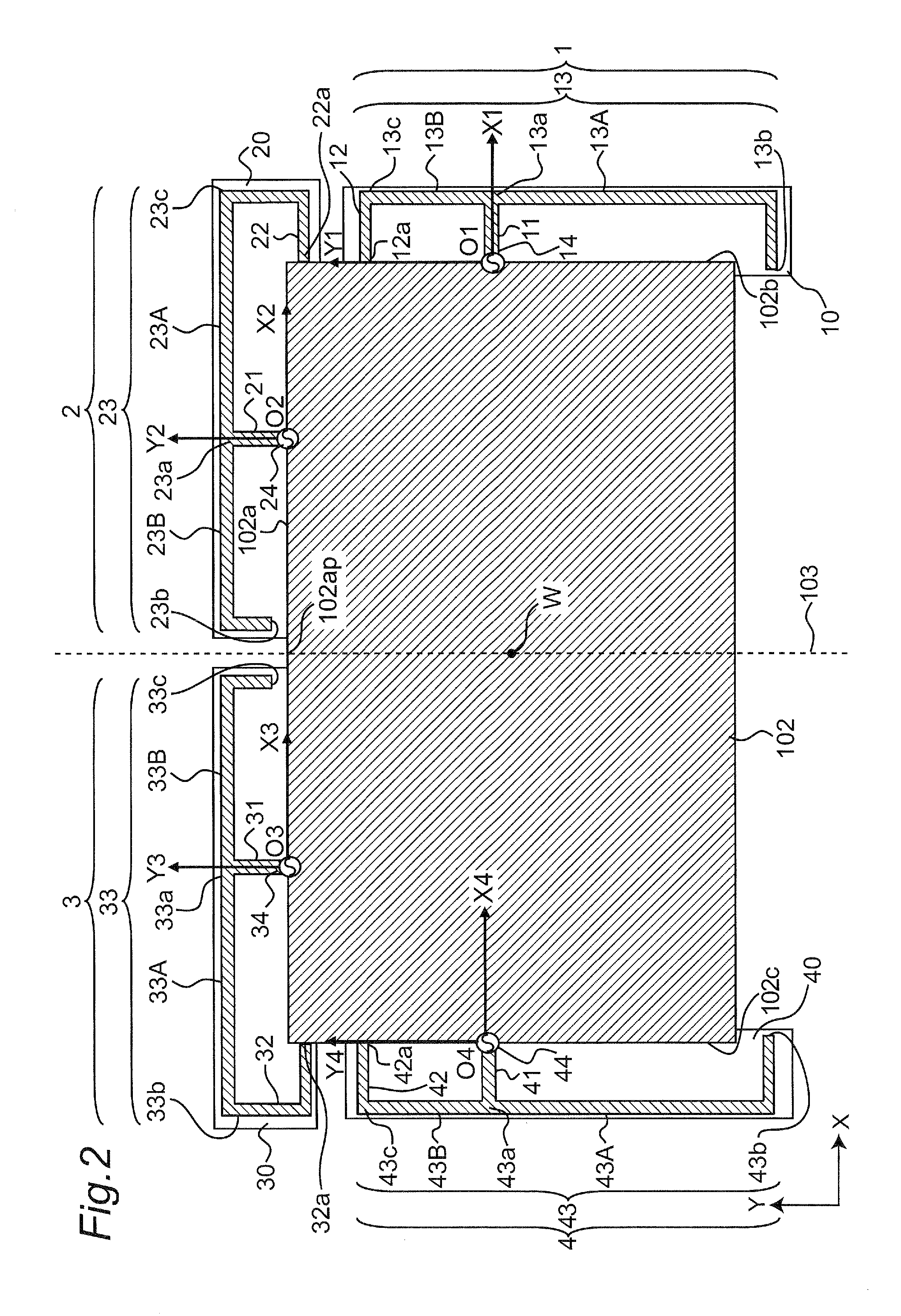
[0118]FIG. 21 is a plan view of an antenna apparatus according to the second embodiment of the present disclosure. The antenna apparatus of the present embodiment differs from the antenna apparatus of the first embodiment in that antennas 201, 202, 203 and 204 are provided in place of the antennas 1, 2, 3 and 4. Only the points of difference from the first embodiments are described below. It is noted that the rightward direction of FIG. 21 is referred to as an X-axis direction, and the upward direction is referred to as a Y-axis direction. Further, a direction opposite to the X-axis direction is referred to as a −X1-axis direction, and a direction opposite to the Y-axis direction is referred to as a −Y-axis direction.
[0119]Referring to FIG. 21, dielectric substrates 110, 120 and 130 are, for example, printed wiring boards, and are each fixed in an identical plane parallel to the surface of the grounding conductor 102. The antenna 201 is provided in the right half region of an edge p...
third embodiment
[0151]FIG. 22 is a plan view of an antenna apparatus according to the third embodiment of the present disclosure. The antenna apparatus of the present embodiment differs from the antenna apparatus of the first embodiment in that antennas 301, 302, 303 and 304 are provided in place of the antennas 1, 2, 3 and 4. Only the points of difference from the first embodiment are described below. It is noted that the rightward direction is referred to as an X-axis direction, and the upward direction is referred to as a Y-axis direction of FIG. 2. Further, a direction opposite to the X-axis direction is referred to as a −X-axis direction, and a direction opposite to the Y-axis direction is referred to as a −Y-axis direction.
[0152]Referring to FIG. 22, dielectric substrates 310, 320 and 330 are, for example, printed wiring boards, and are each fixed in an identical plane parallel to the surface of the grounding conductor 102. Moreover, an antenna 401 is provided at an edge portion 102b, an ante...
PUM
 Abstract
Description
Claims
Application Information
 - R&D
- Intellectual Property
- Life Sciences
- Materials
- Tech Scout
- Unparalleled Data Quality
- Higher Quality Content
- 60% Fewer Hallucinations
Browse by: Latest US Patents, China's latest patents, Technical Efficacy Thesaurus, Application Domain, Technology Topic, Popular Technical Reports.
© 2025 PatSnap. All rights reserved.Legal|Privacy policy|Modern Slavery Act Transparency Statement|Sitemap|About US| Contact US: help@patsnap.com