Fault current limiter

a fault current limiter and fault current technology, applied in the direction of emergency protective circuit arrangement, emergency protective arrangement for limiting excess voltage/current, electric devices, etc., can solve the problems of fcl technologies, increased fault current in the power system, and over-rated devices, etc., to achieve less manufacturing cost, less weight, and more compact

Active Publication Date: 2013-11-28
MERSEN USA EP CORP +1
View PDF1 Cites 27 Cited by
  • Summary
  • Abstract
  • Description
  • Claims
  • Application Information

AI Technical Summary

Benefits of technology

[0013]An advantage of the present invention is the provision of an FCL that is more compact and lighter weight than existing FCLs.
[0014]Another advantage of the present invention is the provision of an FCL that requires fewer components.
[0015]Still another advantage of the present invention is the provision of an FCL that is less expensive to manufacture.
[0016]Still another advantage of the present invention is the provision of an FCL that is more reliable.
[0017]Still another advantage of the present invention is the provision of an FCL that has a low normal operation loss.
[0018]Still another advantage of the present invention is the provision of an FCL that does not require service or replacement after triggering.

Problems solved by technology

The consequence of this trend is that the fault current in the power system is being increased, exceeding the ratings of existing protection devices, e.g., circuit breakers, relays and fuses.
However, device upgrade is generally not economically viable, considering the enormous number of devices that need replacement.
Each of these existing FCL technologies has drawbacks (e.g., high operation losses, bulky size and servicing / part replacement issues).
Most SSFCLs and some SCFCLs are subjected to switching losses during normal operation.
For example, the Is-limiter can raise safety concerns because it is not fail-safe, that is, correct operation of the Is-limiter cannot be tested without destroying the Is-limiter (i.e., the parallel fuse).
Furthermore, supply of pyrotechnic materials are regulated and constrained by the U.S. Department of Defense, thereby resulting in supply problems and increased manufacturing costs.
In addition, replacement of the parallel fuse is required after each triggering, thus leading to high operating cost.
These component requirements result in high manufacturing costs for the NSCFCL.

Method used


Image

  • Fault current limiter
  • Fault current limiter
  • Fault current limiter

Examples


example

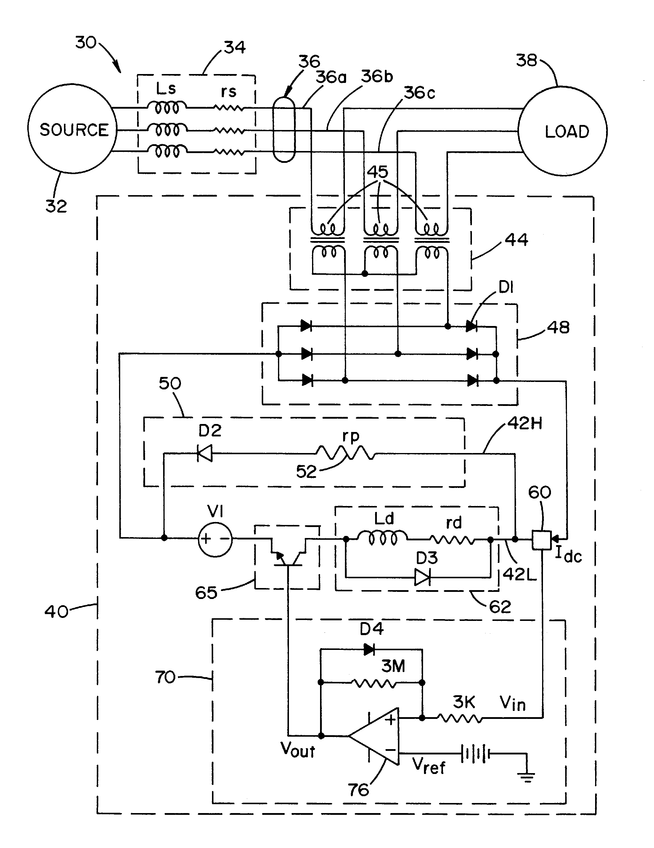
[0077]Example FCL 40 will now be described with reference to FIG. 5 and TABLE 1. TABLE 1 provides a list of major components selected for the sample prototype.

TABLE 1DevicePartDescriptioncurrentCR MAGNETICS1:1 ratio, 40 A, 1.5 lbs.transformers10WP-00545rectifierDIODES Inc.1000 V reverse voltagediodes D110A07-Tforrectifier 48switchingFAIRCHILD600 V, 20 A 3-phase IGBTunit 65FSAM20SH60Ainverter bridge with drivers, 40 AIGBT collector current (peak)dischargingYageo80 W, 15 Ωresistor 52AHA80AJB-15R-NDblockingDIODES Inc.1.5 A surface mount glassdiode D2S2AApassivated rectifierreactorMURATA680 μH, 3.1 A, quantity = 6inductor1400 Seriescoil Ld1468431CsensingHoneywellminiature ratiometric linear Hall-circuit 60CSLH3A45effect sensor

[0078]Current transformers 45 have a low stress rating during normal operation (30V, 5A and 210 W), and are highly stressed during a fault condition (450V, 30A and 14 kW). Since the fault condition typically lasts for only about 200 ms, current transformers 45 can ...


PUM


Abstract

A fault current limiter (FCL) for limiting a fault current in a power line during a fault condition. The FCL includes a magnetic coupling circuit for monitoring current in the power line through magnetic coupling; a sensing circuit for sensing the current in the power line and providing a signal indicative of the sensed current; a control circuit receiving the signal indicative of the sensed current in the power line and determining whether the sensed current indicates that the fault condition exists; and high and low impedance paths that are connected in parallel. The high impedance path includes a discharging impedance circuit for limiting the fault current. The low impedance path includes a reactor circuit and a switching unit having an ON state for conducting current through the low impedance path and an OFF state for conducting current through the high impedance path.

Description

FIELD OF THE INVENTION[0001]The present invention relates generally to fault current limiters, and more particularly to a non-superconducting fault current limiter.BACKGROUND OF THE INVENTION[0002]As the demand for electric power increases, new power sources (such as Independent Power Producers (IPPs) and Distributed Generators (DGs)) are being added to the power grid. The consequence of this trend is that the fault current in the power system is being increased, exceeding the ratings of existing protection devices, e.g., circuit breakers, relays and fuses.[0003]The IPPs, installed in parallel with existing generators, decrease the equivalent source impedance of the grid. Furthermore, the DGs are usually placed close to the load and the fault. Therefore, the impedance from the DGs to fault is also decreased. The effect of smaller impedance in the network is that the fault current might rise above the rated limits of the existing protection devices. In order to protect equipment (e.g...

Claims


Application Information

Patent Timeline
Patent Type & Authority Applications(United States)
IPC IPC(8): H02H9/02
CPCH02H9/02
Inventor CHEN, SONGLI, PENGLEHMAN, BRADLEYDE PALMA, GIANFRANCO
Owner MERSEN USA EP CORP
Why Eureka
Try Eureka