Push-pull converter and modulation method for controlling a push-pull converter

a technology of push-pull converter and modulation method, which is applied in the direction of electric variable regulation, process and machine control, instruments, etc., can solve the problems of power loss, reduce the number of switchable components, simplify the control of the push-pull converter, and reduce the complexity of the measurement technology for detecting exact changeover time points

Active Publication Date: 2013-11-28
ROBERT BOSCH GMBH
View PDF6 Cites 23 Cited by
  • Summary
  • Abstract
  • Description
  • Claims
  • Application Information

AI Technical Summary

Benefits of technology

[0016]It is a concept of the invention to reduce the number of switchable components in a push-pull converter. This can be achieved through the use of a suitable modulation method.
[0017]By reducing the number of switchable components, the control of the push-pull converter can be simplified at the same time because the complexity of the measurement technology for detecting exact changeover time points is reduced. In addition, the inventive modulation method is robust with respect to fluctuations of the adjusted operating point, for example as a result of a change in the attached output load. Moreover, when fluctuations in the attached ou

Problems solved by technology

Power losses resulting from switching processes, which in each case are implemented in

Method used


Image

  • Push-pull converter and modulation method for controlling a push-pull converter
  • Push-pull converter and modulation method for controlling a push-pull converter
  • Push-pull converter and modulation method for controlling a push-pull converter

Examples


Embodiment Construction

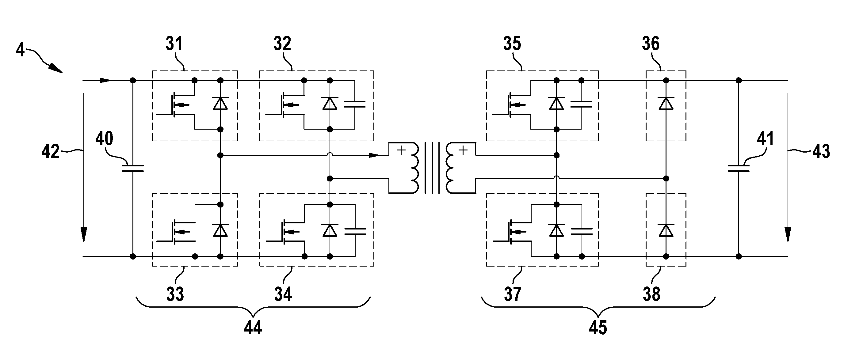
[0031]FIG. 3 shows a schematic depiction of a push-pull converter 4 according to one embodiment of the invention. The push-pull converter 4 comprises a primary-side input converter circuit 44 with the first switching devices 31, 32, 33, and 34. The input converter circuit 44 is designed to convert an input DC voltage, which drops across said input converter circuit 44, into a primary-side AC voltage in a primary-side winding of a transformer 39. Said input converter circuit 44 is configured in a full-bridge circuit as in the push-pull converter from FIG. 2; and therefore the switching devices 31 and 33 form a first primary-side semi-bridge comprising a center tap, which is connected to a first connection of the primary-side winding of the transformer 39, and the switching devices 32 and 34 form a second primary-side semi-bridge comprising a center tap, which is connected to a second connection of the primary-side winding of the transformer 39. Provision can be made to dispose an ext...


PUM


Abstract

The invention relates to a push-pull converter (4) comprising a primary-side input converter circuit (44) with a plurality of primary-side switching devices (31, 32, 33, 34) in a full-bridge circuit, said input converter circuit being designed to convert an input DC voltage (42) into a first AC voltage, and comprising a transformer (39) with a primary-side winding and a ON secondary-side winding, said transformer being designed to receive the first AC voltage on the primary-side winding and to generate a second AC voltage on the secondary-side winding. The push-pull converter also comprises a secondary-side output converter circuit (45) which is designed to convert the second AC voltage into an output DC voltage (43), comprising a first semi-bridge circuit, said semi-bridge circuit comprising a first secondary-side switching device (35), a second secondary-side switching device (37), and a first center to that is connected to a first connection of the secondary-side winding. The secondary-side output converter circuit also comprises a second semi-bridge circuit which comprises a first secondary-side diode (36), a second secondary-side diode (38), and a second center tap which is connected to a second connection of the secondary-side winding, said second semi-bridge circuit not comprising a switchable component.

Description

BACKGROUND OF THE INVENTION[0001]The invention relates to a push-pull converter and a modulation method for controlling a push-pull converter.[0002]Electric vehicles frequently have a device besides the drive system for charging the battery. Such a charging device facilitates in a simple way the charging of the electric energy storage of the electric vehicle at any power outlet. To this end, the charging device produces a DC voltage for charging the fraction battery from the public low voltage network.[0003]An option for the embodiment of a charging device 10 for a vehicle with an electric drive is shown in FIG. 1. The charging device 10 has a power factor correction 2 (PFC) which is connected to an outer conductor 1a and a neutral conductor 1b of a public low voltage network. The power factor correction 2 is designed to extract sinusoidal currents from the supply network and to transfer said currents to a DC converter 4 via an intermediate circuit comprising an intermediate circuit...

Claims


Application Information

Patent Timeline
IPC IPC(8): H02M3/28
CPCH02M3/28H02M3/33592Y02B70/10H02M1/0048H02M3/33573
Inventor HEMBACH, FLORIANVAN BOOVEN, CHRISTOPH
Owner ROBERT BOSCH GMBH
Why Eureka
Try Eureka