Centrifuge, rotor for centrifuge, and sample container for centrifuge

a centrifuge and sample container technology, applied in the field of centrifuges, can solve the problems of increasing the installation area of the centrifuge, increasing the price of the centrifuge, and the size of the centrifuge rotor chamber,

Inactive Publication Date: 2013-11-28
KOKI HLDG CO LTD
View PDF10 Cites 12 Cited by
  • Summary
  • Abstract
  • Description
  • Claims
  • Application Information

AI Technical Summary

Benefits of technology

[0009]In general, to efficiently collect target substances from a liquid sample in a centrifugal process, the rotation speed of the rotor is increased to increase the centrifugal acceleration to be applied to the liquid sample to enhance a centrifugal effect so that the target substances are quickly settled, or the amount of the sample that can be processed at one time is increased so that a collection ratio is improved. Also, for a reduction in cost for a centrifugal operation, it is important to not only inexpensively configure a centrifuge including sample containers and a rotor but also increase the sample amount that can be centrifuged at one time to increase the amount of work done. To centrifuge a large amount of the liquid sample at one time, it is effective to increase the number of sample containers for use in the rotor and to increase the capacity of each sample container. However, to increase the capacity of the conventional cylindrical sample container, the outer diameter or the height of the body part 151 has to be increased. In that case, interference occurs between adjacent sample-container holding holes of the rotor, and therefore the arrangement positions of the holding holes have to be shifted away from the rotation center in a radial direction (to an outer circumferential side). As a result, the diameter of the rotor itself is increased to increase the mass, thereby degrading portability of the rotor by the operator and attachability to the centrifuge.
[0010]The increase in diameter of the rotor leads to an increase in air resistance (windage loss) at the time of high-speed rotation in the centrifuge. To address this, the output of a driving device of the centrifuge has to be increased, and the output of a cooling device part for cooling the rotor has to be increased. Moreover, with the increase of the diameter of the rotor, the size of the rotor chamber of the centrifuge has to be also increased, thereby posing problems of increasing the installation area of the centrifuge and increasing the price of the centrifuge. In the course of solving these problems, the inventors paid attention to the fact that a component portion of the rotor causing an increase in weight (hereinafter referred to as a “superfluous portion”) is present between adjacent sample-container holding holes when the rotor having cylindrically-shaped sample containers arranged therein is viewed from above, and tried an improvement of reducing this superfluous portion as much as possible. Furthermore, in the course of this improvement, the inventors found that a superfluous portion near the outer circumference of the rotor is a cause of increasing the mass of the rotor and a centrifugal load applied to this superfluous portion is a factor in decreasing the strength of the rotor.
[0011]The present invention has been made in view of the background described above, and a preferred aim of the present invention is to prevent a sample container for a centrifuge, having an increased sample amount that can be centrifuged at one time, from being broken or degraded due to a centrifugal force at the time of operation.

Problems solved by technology

Moreover, with the increase of the diameter of the rotor, the size of the rotor chamber of the centrifuge has to be also increased, thereby posing problems of increasing the installation area of the centrifuge and increasing the price of the centrifuge.
Furthermore, in the course of this improvement, the inventors found that a superfluous portion near the outer circumference of the rotor is a cause of increasing the mass of the rotor and a centrifugal load applied to this superfluous portion is a factor in decreasing the strength of the rotor.

Method used


Image

  • Centrifuge, rotor for centrifuge, and sample container for centrifuge
  • Centrifuge, rotor for centrifuge, and sample container for centrifuge
  • Centrifuge, rotor for centrifuge, and sample container for centrifuge

Examples


first example

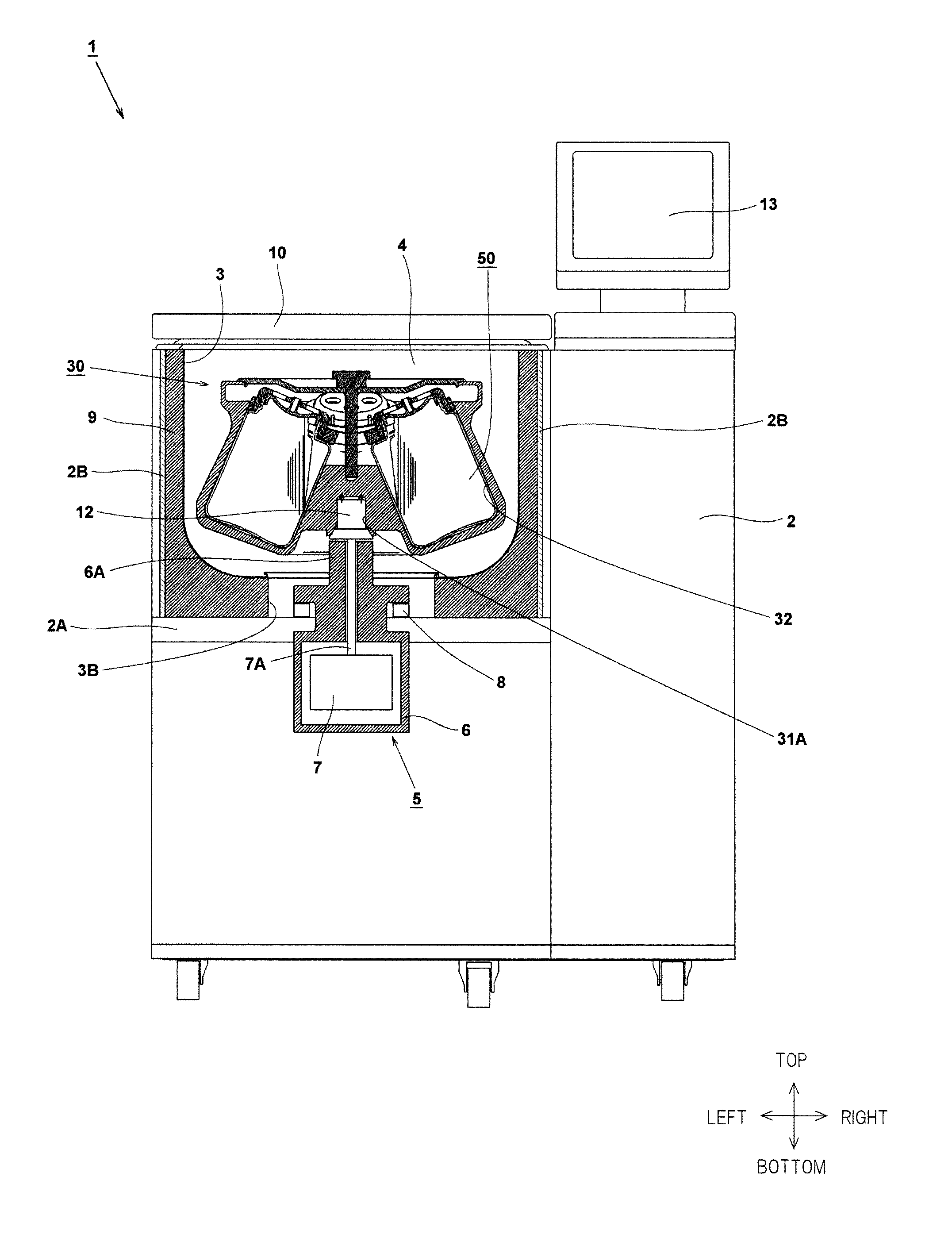
[0034]Hereinafter, a first embodiment of the present invention will be described based on the drawings. Note in the drawings described below that the same portions are provided with the same reference numeral, and repetitive descriptions will omitted. Also, it is assumed in the specification that vertical and horizontal directions of a centrifuge are those indicated in FIG. 1 and a vertical direction of a single sample container is a direction indicated in FIG. 5.

[0035]FIG. 1 is a front view of a centrifuge (a centrifugal machine) of the present invention, with its part illustrated in a cross-sectional view. The centrifuge 1 includes a rectangular-box-shaped casing 2 having an inside space partitioned by a horizontal partition plate 2A into two stages, upper and lower. The upper-stage space obtained by partitioning is provided with a bowl-shaped chamber 3 having its upper surface open. Around the outer circumference of the chamber 3, a coolant circulation pipe not shown is adhered. ...

second example

[0057]Next, a second embodiment of the present invention will be described with reference to FIGS. 9 to 11. In the second embodiment, a sample container has a cylindrical sectional shape, and the container has a smaller opening of a lid part compared with the outer shape of a main body portion of the container. In this sample container, a cap part having a neck support member is used. This structure is to achieve, by using the cap unit having the neck support member that has been used also in the first embodiment in the cylindrical sample container, a further increase in capacity compared with the conventional sample container and a further increase in centrifugal speed by using an operation of holding the opening by the neck support member.

[0058]FIG. 9 is a perspective view of the outer appearance of a sample container (a sample container for a centrifuge) 250 of the second embodiment of the present invention. The sample container 250 is configured of a body part 251 and a cap part...


PUM


Abstract

A sample container includes a body part which can accommodate a sample and a cap part that can be mounted on the non-circular body part. On the cap part, a neck support member is set for filling a space between an outer lid and a holding hole of a rotor body. The neck support member is configured to be able to be attached to and removed from the outer lid and to be able to relatively rotate with respect to the outer lid. By mounting the outer lid on the body part, the neck support member can also be mounted at the same time. The neck support member is arranged so as to be interposed between the outer lid and shoulder parts of the body part in an axial direction. The neck support member has a lower surface formed so as to correspond to the shape of the shoulder parts.

Description

CROSS-REFERENCE TO RELATED APPLICATION[0001]The present application claims priorities from Japanese Patent Application No. 2012-117322 filed on May 23, 2012, and Japanese Patent Application No. 2013-085703 filed on Apr. 16, 2013, the contents of which are hereby incorporated by reference into this application.TECHNICAL FIELD OF THE INVENTION[0002]The present invention relates to centrifuges for use in the fields of medical science, pharmaceutical science, genetic engineering, and others, and relates to a sample container in a cylindrical or non-cylindrical shape for a centrifuge (a centrifugal machine) having an angle rotor.BACKGROUND OF THE INVENTION[0003]A centrifuge for use in separation of a liquid sample includes a rotor which holds a plurality of sample containers having the liquid sample accommodated therein in sample-container holding holes equally arranged on the circumference of a circle and a driving means such as a motor for driving the rotor for rotation. With the rotor...

Claims


Application Information

Patent Timeline
Patent Type & Authority Applications(United States)
IPC IPC(8): B04B7/08
CPCB04B7/08B01L3/50825B04B5/0414B01L3/5021
Inventor ASAKURA, KENNEMOTO, KENICHIKITAZAWA, YOSHIMITSU
Owner KOKI HLDG CO LTD
Why Eureka
Try Eureka