Turbomachine combustor nozzle including a monolithic nozzle component and method of forming the same

a combustor nozzle and combustor nozzle technology, which is applied in the field of combustor nozzles of combustor nozzles having monolithic nozzle components, can solve the problems of nitrogen oxide levels (nox)

Active Publication Date: 2013-12-05
GENERAL ELECTRIC CO
View PDF7 Cites 34 Cited by
  • Summary
  • Abstract
  • Description
  • Claims
  • Application Information

AI Technical Summary

Problems solved by technology

Unfortunately, higher gas stream temperatures produce higher levels of nitrogen oxide (NOx), an emission that is subject to both federal and state regulation.

Method used


Image

  • Turbomachine combustor nozzle including a monolithic nozzle component and method of forming the same
  • Turbomachine combustor nozzle including a monolithic nozzle component and method of forming the same
  • Turbomachine combustor nozzle including a monolithic nozzle component and method of forming the same

Examples


Embodiment Construction

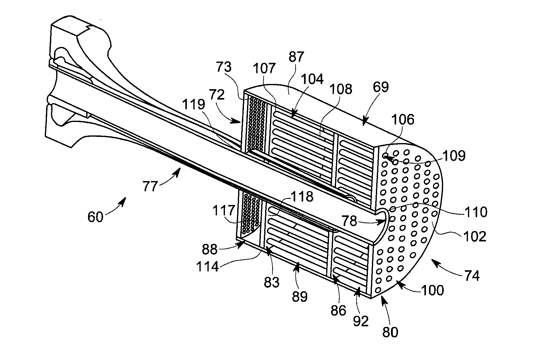
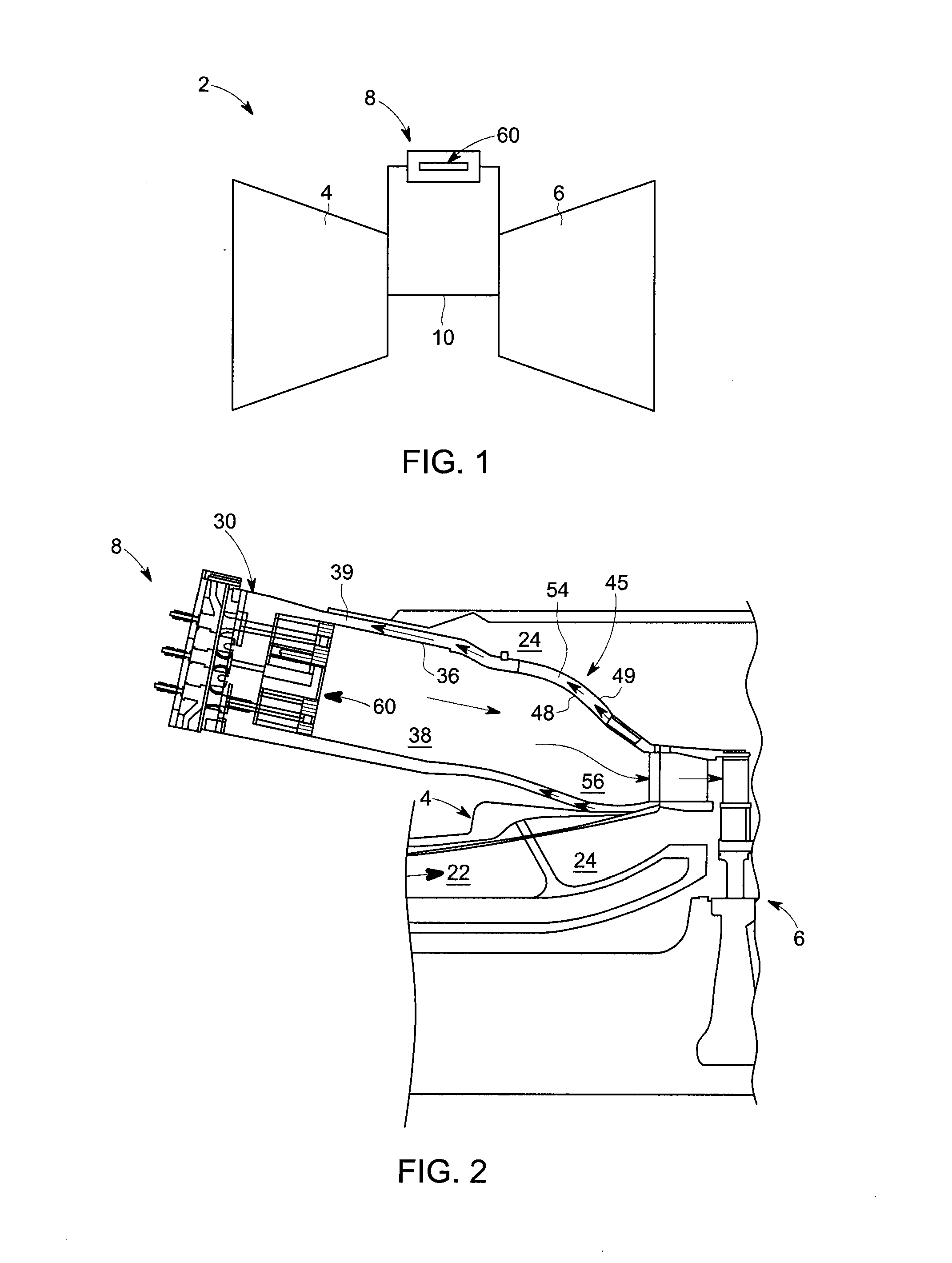
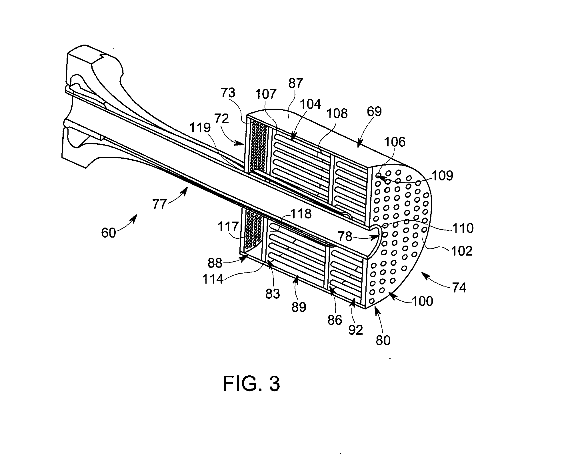
[0019]With initial reference to FIGS. 1 and 2, a turbomachine constructed in accordance with an exemplary embodiment is indicated generally at 2. Turbomachine 2 includes a compressor portion 4 connected to a turbine portion 6 through a combustor assembly 8. Compressor portion 4 is also connected to turbine portion 6 via a common compressor / turbine shaft 10. Compressor portion 4 includes a diffuser 22 and a compressor discharge plenum 24 that are coupled in flow communication with each other and combustor assembly 8. With this arrangement, compressed air is passed through diffuser 22 and compressor discharge plenum 24 into combustor assembly 8. The compressed air is mixed with fuel and combusted to form hot gases. The hot gases are channeled to turbine portion 6. Turbine portion 6 converts thermal energy from the hot gases into mechanical rotational energy.

[0020]Combustor assembly 8 includes a combustor body 30 and a combustor liner 36. As shown, combustor liner 36 is positioned radi...


PUM

PropertyMeasurementUnit
temperatureaaaaaaaaaa
thermal energyaaaaaaaaaa
mechanical energyaaaaaaaaaa

Abstract

A turbomachine combustor nozzle includes a monolithic nozzle component having a plate element and a plurality of nozzle elements. Each of the plurality of nozzle elements includes a first end extending from the plate element to a second end. The plate element and plurality of nozzle elements are formed as a unitary component. A plate member is joined with the nozzle component. The plate member includes an outer edge that defines first and second surfaces and a plurality of openings extending between the first and second surfaces. The plurality of openings are configured and disposed to register with and receive the second end of corresponding ones of the plurality of nozzle elements.

Description

FEDERAL RESEARCH STATEMENT[0001]This invention was made with Government support under Contract Number DE-FC26-05NT42643, awarded by the Department Of Energy. The Government has certain rights in this invention.BACKGROUND OF THE INVENTION[0002]The subject matter disclosed herein relates to the art of turbomachines and, more particularly, to a turbomachine combustor nozzle having a monolithic nozzle component.[0003]In general, gas turbomachines combust a fuel / air mixture that releases heat energy to form a high temperature gas stream. The high temperature gas stream is channeled to a turbine portion via a hot gas path. The turbine portion converts thermal energy from the high temperature gas stream to mechanical energy that rotates a turbine shaft. The turbine portion may be used in a variety of applications, such as for providing power to a pump, an electrical generator, a vehicle, or the like.[0004]In a gas turbomachine, engine efficiency increases as combustion gas stream temperatu...

Claims


Application Information

Patent Timeline
Patent Type & Authority Applications(United States)
IPC IPC(8): F23R3/28B23P11/00F23R3/10
CPCF23R3/283F23R3/286F23R2900/00017F23R2900/00018Y10T29/49323
Inventor STOIA, LUCAS JOHNMELTON, PATRICK BENEDICTJOHNSON, THOMAS EDWARDSTEVENSON, CHRISTIAN XAVIERVANSELOW, JOHN DRAKEWESTMORELAND, JAMES HAROLD
Owner GENERAL ELECTRIC CO
Why Eureka
Try Eureka